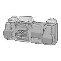
CD-K1861V
– 60 –
ICK1 VHiM65845FP-1: MIC AMP (IM65845FP)
Pin No. Port Name
Terminal Name
Input/Output
Function
1 Mic 1 input MIC 1 IN Input Mic 1 is connected.
2 ALC 1 contrl ALC 1 — ALC attack recovery time setting C is connected.
3 Mic 1 negative MIC 1 NFIN Input Mic 1 amp. gain is set through feedback circuit.
feedback input
4 Mic 1 output MIC 1 OUT Output Mic 1 amp. gain is set through feedback circuit.
5 Mic 1 volume input MIC 1 VOLIN Input Input after attenuation through extemally provided mic volume.
6 Mic 2 input MIC 2 IN Input Mic 2 is connected.
7 ALC 2 control ALC 2 — ALC attack recovery time setting C is connected.
8 Mic 2 negative MIC 2 NFIN Input Mic 2 amp. gain is set through feedback circuit.
feedback input
9 Mic 2 output MIC 2 OUT Output Mic 2 amp. gain is set through feedback circuit.
10 Mic 2 volume input MIC 2 VOLIN Input Input after attenuation through extemally provided mic volume.
11 Mic output MIC OUT Output Mic 1/Mic 2 mixing output.
12 Low-pass filter 1 input LPF 1 IN Input Prefilter before A/D conversion for digital echo.
13 Low-pass filter 1 output LPF 1 out Output Prefilter before A/D conversion for digital echo.
14 A/D integrator input AD IN TIN Input A/D converting integrator is composed, using externally provided C.
15 A/D integrator output AD IN TOUT Output A/D converting integrator is composed, using externally provided C.
16 A/D control AD CONT — Proper time constant of ADM system A/D conversion is determined.
17 Reference REF — 1/2 Vcc output, filter C is connected.
power output
18 Grounding GND —
19 Power VCC — System reset.
20 D/A control DACONT — Proper time constant of ADM system A/D converslon is determined.
21 D/A integrator input DA IN TIN Input D/A converting integrator is composed, using externally provided C.
22 D/A integrator output DA IN TOUT — D/A converting integrator is composed, using externally provided C.
23 Low-pass filter 2 input LPF 2 IN Input Prefilter before D/A conversion for digital echo.
24 Low-pass filter 2 output LPF 2 OUT Output Prefilter before D/A conversion for digital echo.
25 Echo volume input ECHO VOL IN Input input after attenuation through extemally provided mic volume.
26 Rch line input RLINE IN Input
27 Lch line input LLINE IN —
28 Rch line output RLINE OUT Input Mic system/Line system mixing output.
29 Lch line output LLINE OUT Output Mic system/Line system mixing output.
30 Mic echo output MIC ECHO OUT Input Mic original sound/Echo mixing output.
31 Mic Switch MIC SW Output L;MIC OFF H;MIC ON
32 Clock CLOCK Input CR oscillator;Oscillation buffer provided.
33 Audio Switch 1 AUD SW1 Output Sound selection switch;Audio signal is setected by setting Audio
switches 1 and 2 to L or H.
34 Audio Switch 2 AUD SW2 Input Sound selection switch;Audio signal is setected by setting Audio
switches 1 and 2 to L or H.
35 ALC operating VALC Output ALC operating voltage is set according to applied voltage.
voltage setting
36 Vocal cut filter VCFIL — Frequency components lower than vocal range are slewed.
L - R
L - R
1/2Vcc
4KRAM
AUDIO SOURCE
CONTROL
CLOCK
GENERATOR
LOGIC
ALC
ALC
A / D A / D
R - L
L
REF
LPF1
REF
LPF1
2
3
4
5
1
7
8
9
6
12
13
14
15
11
17
18
19
10
16
22
23
24
25
21
27
28
29
20
26
32
33
34
35
31
30
36
Lin
Rin
VALL
MIC1 IN
MIC1 NFIN
MIC1 OUT
ALC1
ALC2
VOL IN
MIC2 IN
MIC2 NFIN
MIC2 OUT
MIC2 VOLIN
AUDSW1 AUDSW2
VCFIL
CLOCK
REF
Vcc
GND
Lout
Rout
MIC SW
MICECHO
OUT
ECHOVOL IN
LPF2
OUT
DAINT OUT
LPF2 IN
DAINT IN
DACOUT
ADINT ONT
ADINT IN
LPF1
OUT
ADCONT
MIC
OUT
LPF1
IN
Figure 60 BLOCK DIAGRAM OF IC