CD-SW200
2 – 4
[4] CD SECTION
• Adjustment
Since this CD system incorporates the following automatic adjust-
ment functions, readjustment is not needed when replacing the
pickup. Therefore, different PWBs and pickups can be combined
freely.
Each time a disc is changed, these adjustments are performed
automatically. Therefore, playback of each disc can be performed
under optimum conditions.
Items adjusted automatically
1) Offset adjustment (The offset voltage between the head amplifier
output and the VREF reference voltage is compensated inside the
IC.)
* Focus offset adjustment
* Tracking offset adjustment
2) Tracking balance adjustment
3) Gain adjustment (The gain is compensated inside the IC so that the
loop gain at the gain crossover frequency will be 0 dB.)
* Focus gain adjustment
* Tracking gain adjustment
[5] CD section
CD Error code description
* 'CHECKING'
If Error is detected, 'CHECKING' will be displayed instead of 'ER-
CD**'. 'ER-CD**' display will only be displayed when error had been
detected for the 5th times.
[6] Standard Specification of Stereo System Error Message Display Contents
(*) CHECKING:
If CD changer mechanism error is detected, ‘CHECKING’ will be dis-
play instead of ‘ER-CD**’. ‘ER-CD**’ display will only be display when
error had been detected for the 5 th times.
Speaker abnormal detection and +B PROTECTION display
In case speaker abnormal detection or +B PROTECTION had
occurred, the unit will automatically enter to stand-by mode and Timer
indicator will Flashing as below.
+B PROTECTION is condition when irregular process occur on power
supply line.
BEFORE TRANSPORTING THE UNIT
The following process need to be taken after set tapering/parts
replacement.
1. Press the ON/STAND-BY button to enter stand-by mode.
2. While pressing down the button and the X-BASS/DEMO but-
ton, press the ON/STAND-BY button. The Micro Computer version
number will be displayed as “CN******”.
3. Press OPEN/CLOSE button until “WAIT”→ “FINISHED” appears.
4. Unplug the AC cord and the unit is ready for transporting.
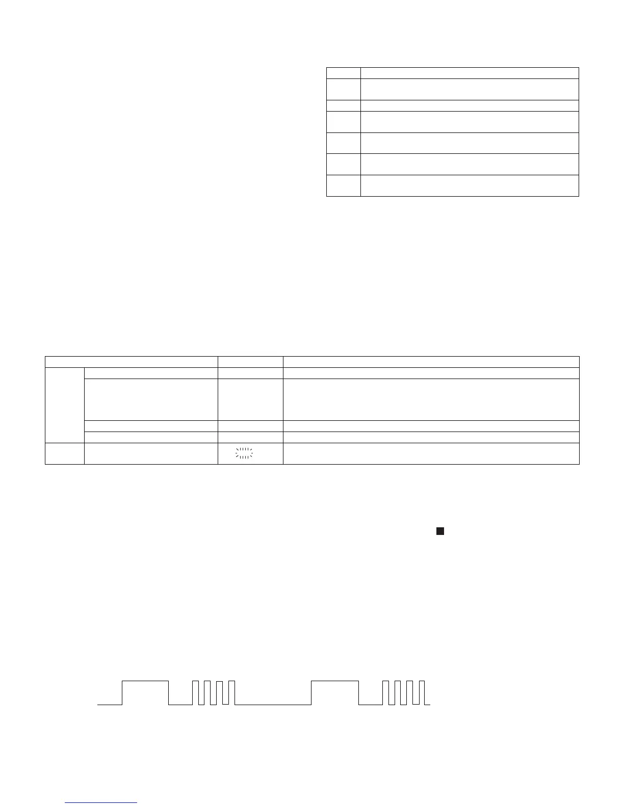
Error Explanation
01 When Pickup set inner position, inner switch cannot detect
'ON' level for 10 secs.
10* CAM error. Can't detect CAM switch when CAM is moving.
11* When it detect cam operation error during initialize pro-
cess.
20* TRAY error. Can't detect TRAY switch when TRAY is mov-
ing.
21* When it detect TRAY operation error during initialize pro-
cess.
31 When it change to CD function, DSP cannot read initial
data.
Error Contents Display Notes
CD Pickup Mechanism Error. 'ER-CD01' PU-IN SW Detection NG.
CD Changer Mechanism Error. 'ER-CD**' (*) 10: CAM SW Detection NG during normal operation
11: CAM SW Detection NG during initialize process
20:TRAY SW Detection NG during normal operation
21:TRAY SW Detection NG during initialize process
CD DSP Communication Error. 'ER-CD31' DSP COMMUNICATION ERROR.
Focus Not Match/IL Time Over. 'NO DISC'
TUNER PLL Unlock. PLL Unlock.
FM 87.5 MHz
TIMER
LED
ON FLASHING
1 FRAME
(REPEAT)
FLASHINGON
NO. 1
NO. 2
NO.1:+BPROTECTION
NO. 2 : Speaker abnormal
Example: In case of speaker abnormal
NO. 2
NO. 1
OFF OFF OFF OFF