CHAPTER 5. REMOVING THE
PRINTER UNIT (For
ER-A310 & ER-A330)
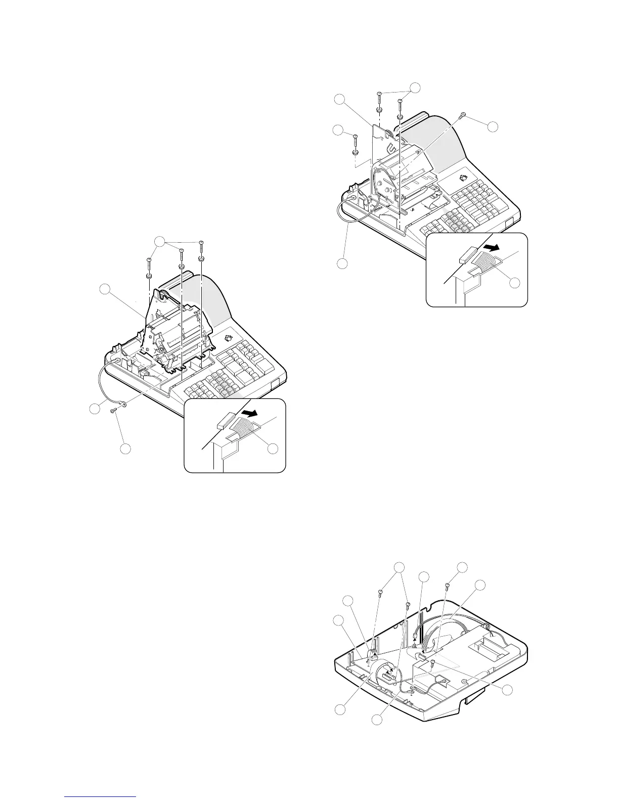
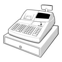
1. ER-A310
1) Remove the top cabinet.
2) Remove the printer cable 1 from the main PWB.
3) Remove the three screws 2 .
4) Remove the screw 3 and grounding wire 4 .
5) Remove the printer unit 5 from the top cabinet.
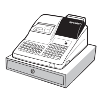
2. ER-A330
1) Remove the top cabinet.
2) Remove the printer cable 1 from the main PWB.
3) Remove the three screws 2 .
4) Remove the screw 3 and grounding wire 4 .
5) Remove the printer unit 5 from the top cabinet.
CHAPTER 6. REMOVING THE MAIN
PWB (For ER-A310 &
ER-A330)
1. ER-A310/A330
1) Remove the top cabinet.
2) Remove the printer unit.
3) Remove the following connector cables from the main PWB.
Dry battery cable 1
Pop up display cable 2
Note: The pop-up cable is fixed with the holder not to make
contact with the heat radiating plate on the main PWB. Be
careful of it when installing.
Mode switch cable 3
Keyboard cable 4
4) Remove the screw 5 and grounding wire 6 .
5) Remove the free screws 7 and main PWB 8 .
1
2
3
4
5