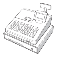
CHAPTER 10. ONE HOLE CLERK
KEY KIT
*
Standard provision for the TQ, TR, and TS versions of the ER-
A330.
1. Component list
No. PARTS CODE DESCRIPTION Q’ty
1
LKGIW7375BHZZ
Clerk SW body 1
2
LKGIM7377BH01
Clerk key 1 2
3
LKGIM7377BH02
Clerk key 2 2
4
LKGIM7377BH03
Clerk key 3 2
5
LKGIM7377BH04
Clerk key 4 2
6
LKGIM7377BH05
Clerk key 5 2
7
LKGIM7377BH06
Clerk key 6 2
8
QCNW-7818BHZZ
Clerk key cable (5P) 1
9
QCNCW2423BH0E
Clerk connector (5P) 1
10
LANGT7602BHZZ
Clerk switch angle 1
11
XJSSD26P08000
Screw 1
12
XEBSD30P08000
Screw 2
13
GFTAF6922BHZZ
Clerk cover "B" 1
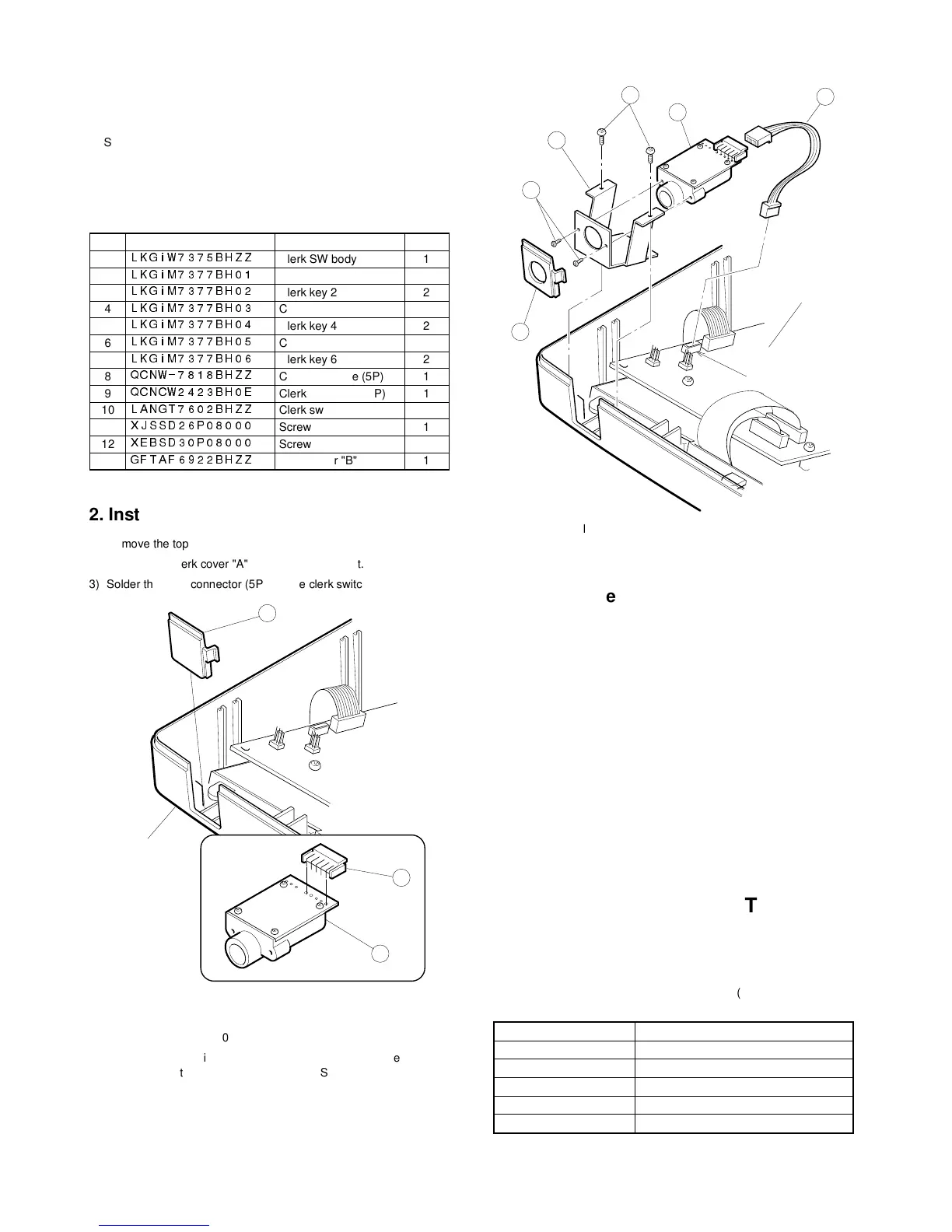
2. Installation procedure
1) Remove the top cabinet.
2) Remove the clerk cover "A"
1
from the top cabinet.
3) Solder the clerk connector (5P)
2
to the clerk switch body
3
.
4) Connect the clerk key cable (5P)
4
to the clerk switch body
3
.
5) Attach the clerk angle
5
to the clerk switch body
3
and fix with
screw
6
(XJSSD26P08000).
6) Install the clerk switch body
3
to the clerk cover "B"
7
then install it
the top cabinet and fix with screws
8
(XEBSD30P08000).
7) Connect the clerk key cable (5P)
4
to location No. NC9 on the main
PWB.
3. Operation test
CHAPTER 11. KEY TOP KIT
1. Outline
The ER-A460 employs the following key top (option) to allow addi-
tional installation of the key top and change in the key layout.
MODEL NAME DESCRIPTION
ER-11KT7 1 × 1 Key top
ER-12KT7 1 × 2 Key top
ER-22KT7 2 × 2 Key top
ER-11DK7 1 × 1 Dummy key
ER-51DK7 5 × 1 Dummy key
1
Top cabinet
2
3