IM-MT899H/IM-MT899W
– 19 –
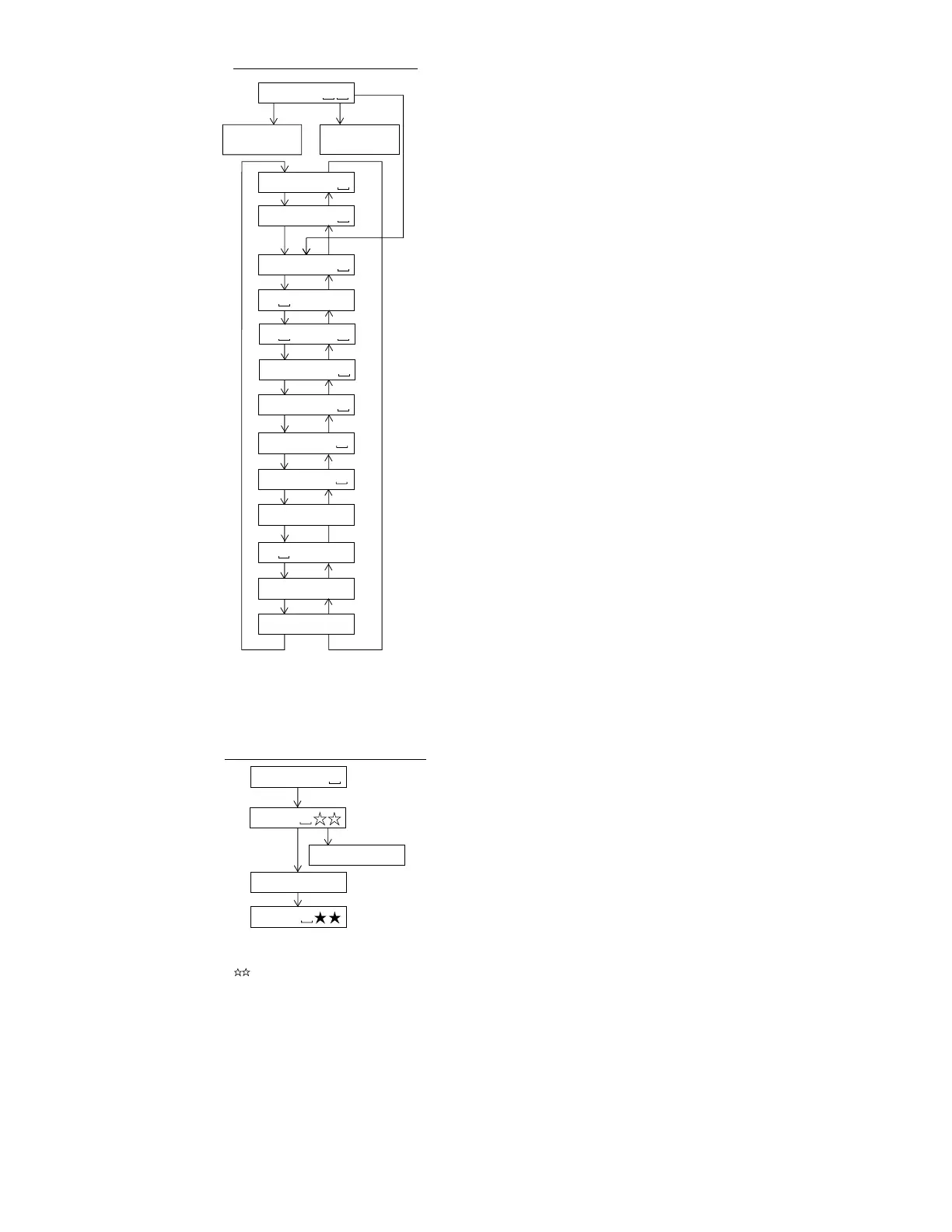
: Test mode stop
: Pre-automatic adjustment menu
: Automatic adjustment menu for production
: ATT auto adjustment menu
: EEPROM setting menu
MODE/
DISPLAY
T E S T
Slide external
periphery move
Slide internal
periphery move
Change of Test Mode Menus
A U T O 1
A U T O J
A U T O 2
SKIP UP SKIP DOWN
SKIP UP SKIP DOWN
SKIP DOWN
SKIP UP SKIP DOWN
SKIP UP SKIP DOWN
SKIP UP SKIP DOWN
SKIP UP SKIP DOWN
T R E C
T P L A Y
SKIP UP SKIP DOWN
SKIP UP SKIP DOWN
: Error history display menu
E E P R O M
SKIP UP SKIP DOWN
SKIP UP
SKIP DOWN
SKIP UP
* When the [STOP] button is pressed in specific menu, the "TEST MODE STOP" state is set.
* When the [VOLUME+] button is pressed in the "TEST MODE STOP" state, the program version
is displayed for 2 seconds.
* When the [VOLUME–] button is pressed in the "TEST MODE STOP" state, all the displays
appear for 2 seconds.
: Pre-manual adjustment menu
: ATT manual adjustment menu
: Continuous playback menu
M A N U 1
: Continuous record menu
M A N U 2
: Test mode normal play menu
E D A T A
N O R M A L
: Digital input signal monitor menu
SKIP UP SKIP DOWN
SKIP UP SKIP DOWN
: Pre-adjustment value check menu
D i n M o n
SKIP UP SKIP DOWN
: ATT adjustment value check menu
R S L T 1
R S L T 2
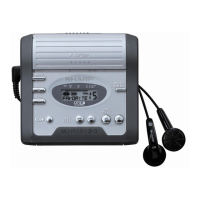
: Preautomatic adjustment menu
Adjustment error
: Preadjustment error (adjustment value output)
: During preautomatic adjustment
Adjustment error
Normal end
: Preadjustment normal end (adjustment value output)
: During ATT automatic adjustment
PLAY
PLAY
A U T O 1
Servo Preautomatic Adjustment
A D J . O K
A D J . N G
A T 2
A T 1
* When the [STOP] button is pressed in specific menu, the "TEST MODE STOP" state is set.
* Move the pickup lens manually to the innermost periphery before performing the servo
preliminary auto adjustment. (Refer to "Change of test mode menus" for the operation method.)
* " " is the internal processing number, the meanings of the numbers are as follows.
0 0 : Thread moving toward the most inner circumference
0 2 : ABEF input offset measurement
0 4 : AB input (ABMAXO) level setting
0 5 : Focus ATT tentative setting
0 6 : Pit section EF input level setting
0 7 : COUT level setting for pit section adjustment
0 8 : Sled external periphery move
0 9 : Groove section EF input level setting
1 0 : COUT level setting for groove section adjustment
1 1 : TCRS input level setting
1 2 : Tracking ATT initial setting
1 3 : AB input (LPFABO) level setting
1 4 : Focus ATT initial setting
1 6 : TCRS input offset measurement
* It is necessary for each test mode where servo operation is made to complete the preliminary
adjustment. (Otherwise, "ErADJ." appears.)
* The preliminary adjustment complete state is stored on the EEPROM (protected field).