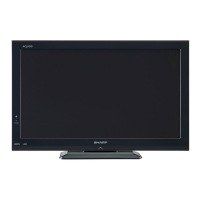
Do you have a question about the Sharp LC-22LE240E and is the answer not in the manual?
Technical details for TV broadcasting, channels, audio, and panel dimensions.
Details on DVB-C transmission standards, demodulation, video, and audio.
Crucial safety warnings for service technicians, including circuit modification and power disconnection.
Guidance on replacement parts and their safety characteristics, emphasizing using identical components.
Guidelines for soldering with lead-free solder, including temperature and tip maintenance.
Instructions for private users on disposing of electrical equipment in the EU and other countries.
Detailed listing and description of all buttons on the remote control handset.
Explanation of the TV's physical buttons and their functions.
Details on various input/output ports located on the back of the TV.
Description of various input/output ports located on the side of the TV.
Important information regarding the TV's power requirements and connection.
Instructions and precautions for connecting and using USB storage devices with the TV.
Steps for connecting a DVD player using an HDMI cable for better quality.
Guide on connecting a PC to the LCD TV for displaying computer screen images.
Steps for turning the TV on, switching to standby, and turning it off completely.
Visual representation and measurements of the TV's physical dimensions.
General overview of the 17MB62 mainboard and its capabilities.
A detailed block diagram illustrating the internal connections and components of the 17MB62 chassis.
Diagram showing the physical placement of major ICs and connectors on the MB62 mainboard.
Description of the tuner module, its bands, and tuning mechanism.
Detailed description and features of the Sony RE216 tuner.
A block diagram illustrating the tuner's application and pinning.
Overview of the AZAD2102B audio amplifier, its power output, and technology.
Key features of the AZAD2102B audio amplifier, including efficiency and protection.
Electrical parameters and test conditions for the audio amplifier under specific ratings.
Diagram and list of the pins for the audio amplifier package.
Description of the TPA3113D2 audio amplifier, its power, and protection features.
Key features of the TPA3113D2 amplifier, including efficiency and protection.
Electrical characteristics and test conditions for the TPA3113D2 amplifier.
Pinout details for the TPA3113D2 audio amplifier IC.
Diagram showing the power socket connections and voltage outputs.
Details of DC/DC converter circuits within the power stage.
Circuit for protecting against over-voltage when using an adaptor.
Power management scheme for the MB62 chassis when using an adaptor.
Power management scheme for the MB62 chassis with PW25/PW26 power supplies.
Power management schemes for the MB62 chassis with different power supply units.
Detailed description of the MSTAR MSD9WB9PT-2 main IC and its modules.
Features and capabilities of the hardware JPEG decoder.
Details on the NTSC/PAL/SECAM video decoding standards supported.
Information on DVI, HDCP, and HDMI input ports, including specifications.
Description of the 2D graphics engine and its capabilities.
Details on the VIF demodulator and its supported standards.
The reset circuit used for initializing the main Mstar IC.
Circuit for controlling power supply to the CI module.
Description of the integrated USB 2.0 interface and its main parts.
Description of the 1Gb DDR2 SDRAM organization and transfer rates.
Key features of the DDR2 SDRAM, including voltage and speed.
Diagram showing the ball locations for the DDR2 SDRAM package.
Block diagram of the scaler and LVDS sockets interface.
Circuit for controlling panel supply to the TCON, managed by the microcontroller.
Description of the MX25L1005 serial Flash memory and its interface.
Key features of the SPI Flash memory.
Absolute maximum ratings for the SPI Flash memory, including voltage and temperature.
Description of the NAND flash memory family and its technology.
Key features of the NAND flash memory, including interface and page/block sizes.
Information about the status register in the NAND flash memory.
Description of the LM1117 series of low dropout voltage regulators.
Key features of the LM1117 regulators, including voltage options and current limit.
Common applications for the LM1117 voltage regulators.
Absolute maximum ratings for the LM1117 regulators.
Description of the MP2012 PWM step-down converter and its capabilities.
Pinout diagram and description for the MP2012 converter.
Description of the RT8283A DC/DC converter, its efficiency, and protection features.
Pinning table for the RT8283A converter.
Description of the MP1583 step-down regulator and its features.
Pinning table for the MP1583 regulator.
Description of the FDC642 P-Channel MOSFET and its process.
Pinning diagram for the FDC642 MOSFET.
Description of the FDC604P P-Channel MOSFET and its optimization.
Pinning diagram for the FDC604P MOSFET.
Pinout details for the SCART connector.
Pinout details for the VGA connector.
Settings for video parameters within the service menu.
Settings for audio parameters within the service menu.
General options settings within the service menu.
Additional options settings within the service menu.
Settings related to TV tuning within the service menu.
Settings for selecting input sources within the service menu.
Information regarding USB operations within the service menu.
Step-by-step instructions for updating the TV's software.
Troubleshooting steps for cases where the TV has no backlight or picture.
Description of the dimming circuit and related checks.
Information related to CI detection and related circuit checks.
Troubleshooting steps for issues causing LED blinking without other operation.
Information about the LED socket and its role in IR functionality.
Troubleshooting steps for USB not working or not being detected.
Troubleshooting steps for no audio output at the headphone jack.
Troubleshooting steps for when there is no signal in TV mode.
Wiring diagram connecting the main board to other components.
Schematic diagram for the tuner and T2 demodulator.
Schematic diagram for the SCART connector and associated circuits.
Schematic diagram for the PC input port.
Schematic diagram for SAV RCA inputs.
Schematic diagram for YPbPr Slim input.
Schematic of audio output circuits.
Schematic of audio input circuits.
Schematic of the audio amplifier for 16" to 24" TVs.
Schematic of the audio amplifier for 26" to 32" TVs.
Diagram for single LVDS FFC connections.
Diagram for double LVDS FFC connections.
Diagram of the power socket and related circuits.
Diagram of the dimming circuit.
Diagram of the short circuit protection circuit.
Diagram of the adapter socket.
Power block diagram for adapter configuration.
Diagram related to the SMPS group within the power supply.
Schematic of the step-up converter for LED backlighting.
Layout diagram of the printed wiring board for the main unit.
List of integrated circuits used in the TV.
List of transistors used in the TV.
List of resistors used in the TV.
Part number and description for the front LED assembly.
List of accessories provided with the TV.
List of packing materials for the TV.
| Screen shape | Flat |
|---|---|
| Response time | 8 ms |
| Display diagonal | 22 \ |
| Display brightness | 250 cd/m² |
| LED backlighting type | Edge-LED |
| Supported video modes | 1080p |
| Contrast ratio (dynamic) | - |
| Display diagonal (metric) | 55 cm |
| Supported graphics resolutions | 1920 x 1080 (HD 1080) |
| 3D | No |
| Annual energy consumption | 32 kWh |
| Product color | Black |
| Panel mounting interface | 75 x 75 mm |
| Analog signal format system | NTSC, PAL, SECAM |
| Digital signal format system | DVB-C, DVB-T |
| RMS rated power | 5 W |
| Number of speakers | 2 |
| HDMI version | 1.3 |
| USB 2.0 ports quantity | USB 2.0 ports have a data transmission speed of 480 Mbps, and are backwards compatible with USB 1.1 ports. You can connect all kinds of peripheral devices to them. |
| S-Video inputs quantity | 0 |
| Video formats supported | DIVX, H.264, MPEG2, MPEG4 |
| Remote control type | RC1910 |
| Power consumption (standby) | 0.5 W |
| Depth (with stand) | 135 mm |
|---|---|
| Height (with stand) | 379 mm |
| Weight (with stand) | 5000 g |
| Depth (without stand) | 36 mm |
| Width (without stand) | 535 mm |
| Height (without stand) | 347 mm |
| Weight (without stand) | - g |