LC-26SA1E/RU, LC-32SA1E/RU
6 – 1
LC-26SA1E
Service Manual
CHAPTER 6. TROUBLESHOOTING TABLE
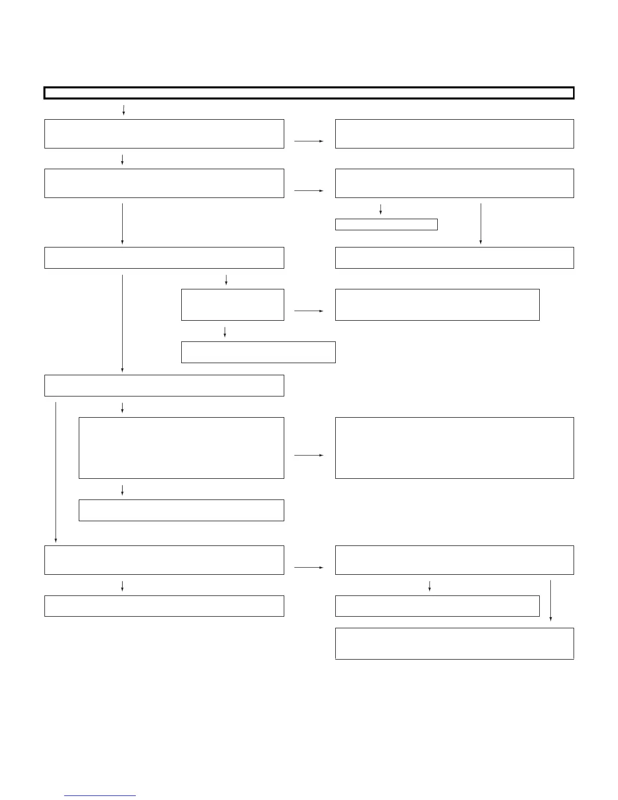
[1] TROBLESHOOTING TABLE
Power unit operation check.
Are the power cord and harness in the unit properly connected? NO Connect the power cord and harness properly, and turn on the
power.
YES
Is F701 normal? NO Are both ends of C704, C707 (26) and C705 (32) short-circuited
when checking their resistance values?
YES
NO
YES
Replace F701.
Is a voltage of BU5V applied to pin (20) of P701?
(Set the main power SW to OFF.)
C704 ••• Check VA701, VA702 and D701.
C707 (26)/C705 (32) ••• Check IC704 and 705.
YES
NO
Is a voltage of approx.
8 - 15V to pin (4) of
IC705?
NO Check IC705, IC708, D725 and Q724.
YES
Check short circuit of 5V line (D737,
C752, etc.).
Is it a symptom that the relay clatters twice as soon as the main
power SW is set to ON and the power is not supplied?
NO
YES
Does the same symptom appear even if R858 (2.7k) is
removed and the power is supplied again?
NO
Check IC704, D728, D762 and D736. If there are no problems,
check the resistance value between pins (1) and (6) of P704.
When the value is low (several Ω - several hundred Ω),
disconnect P704. If the value is still low, the parts of 24V line are
defective. When the resistance value is several kΩ, check the
inverter unit.
YES
Check Q724, D731, D734, IC707, D751, D753, D754,
D741, D759 and D746.
Does a relay noise sound? (Once) NO Are PCON1 and 2 [pins (1) and (2) of P702] at Hi (3V or more)?
YES YES
NO
Check peripheral circuits of D738, R828 and D735. Check peripheral circuits of Q712, Q713, Q721, Q723
and RY701.
There is a possibility that control by P-CON is not performed
properly. Check whether the “PS-ON” and “PS-ON2” signals are
sent from pins (97) and (91) of IC1710 (FPGA) of MAIN-UNIT.