LC-42D43U
3 – 1
LC-42D43U
Service Manual
CHAPTER 3. ADJUSTMENT
[1] ADJUSTMENT PROCEDURE
The adjustment values are set to the optimum conditions at the factory before shipping. If a value should become improper or an adjustment is
required due to part replacement, make an adjustment according to the following procedure.
1. After replacement of any PWB unit and/or IC for repair, please note the following.
When replacing the following units, make sure to prepare the new units loaded with updated software.
MAIN Unit: DUNTKD862FM04.
AV TERMINAL Unit: DUNTKD935FM03
2. Signal Adjustment
2.1. White balance adjustment
Adjustment item Adjustment conditions Adjustment procedure
1 Setting For detailed adjustment procedure, refer to “Kameyama Model Integral Monitor WB
Adjustment Specifications V1.4”.
1) Make the following settings for the set.
AV MODE: [DYNAMIC]
Backlight: +16
Aging time: Min. 60 minutes
2) Connect the white balance adjustment tool to the set.
2 Automatic adjust-
ment execution
[Command]
Process mode
KRSW0001
KKT10037
Setting
KYOF0000
OSDS0001
SBSL0016
Multi-point adjustment
mode
MSET0001
Adjustment value initializa-
tion
MSET0004
Point 6
LEV60232
(WBI60928)
MG6G****
MG6B****
MG6R****
Point 5
LEV50200
(WBI50800)
MG5G****
MG5B****
MG5R****
[Adjustment procedure]
1) Using the remote controller, transmit the “monitor adjustment process” code.
2) Set the 6th point to the specified gradation level. With the strongest color being fixed,
turn down the R, G and B settings to their reference levels.
3) Set the 5th point to the specified gradation level. Correct the G setting (860 x 6th-
point G setting / 920) (rounded off), and make the R and B settings to their reference
levels.
4) Set the 4th point to the specified gradation level. Correct the G setting (736 x 6th-
point G setting / 920) (rounded off), and make the R and B settings to their reference
levels.
5) Set the 3rd point to the specified gradation level. Correct the G setting (512 x 6th-
point G setting / 920) (rounded off), and make the R and B settings to their reference
levels.
6) Set the 2nd point to the specified gradation level. Correct the G setting (256 x 6th-
point G setting / 920) (rounded off), and make the R and B settings to their reference
levels.
7) Set the 1st point to the specified gradation level. Correct the G setting (192 x 6th-
point G setting / 920) (rounded off), and make the R and B settings to their reference
levels.
8) With the MSET0003 command, write the adjustment values and turn off the AC
power.
* Initial R, G and B settings at point 6: Gradation level set at 920
* Initial R, G and B settings at points 1 thru 5: Corrected G setting at each point
(This is because the adjustment is made to achieve the same remainder of RGB setting /
4 at each point.)
[Adjustment value]
•As per the “standard set” submitted by Engineering Department
“LC-42HT3U” Teaching set
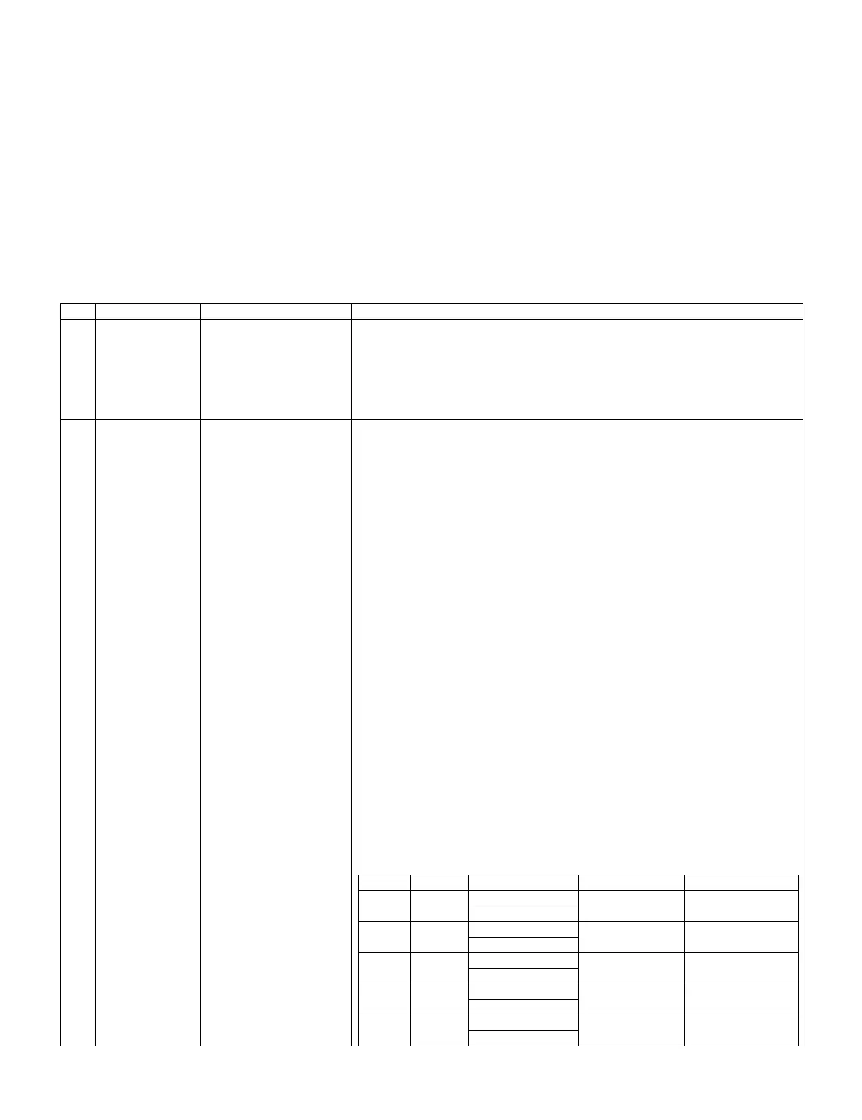
[Adjustment reference] Instrument: Minolta CA-210 Engineering instrument
Point 4 Level Reference Adj. spec Ins. spec
LEV40164 Point 6 928 X=0.272 ±0.0025 ±0.0050
(WBI40656) y=0.277
MG4G**** Point 5 800 X=0.272 ±0.0025 ±0.0050
MG4B**** y=0.277
MG4R**** Point 4 656 X=0.272 ±0.0035 ±0.0070
y=0.277
Point 3 Point 3 528 X=0.272 ±0.0050 ±0.0100
LEV30132 y=0.277
(WBI30528) Point 2 352 X=0.272 ±0.0080 ±0.0150
MG3G**** y=0.277