EasyManua.ls Logo

Sharp LC-42D65U User Manual

Sharp LC-42D65U
114 pages
To Next Page IconTo Next Page
Page #1 background imageLoading...
Page #1 background image
SERVICE MANUAL
Parts marked with " " are important for maintaining the safety of the set. Be sure to replace these parts with specified ones for maintaining the
safety and performance of the set.
This document has been published to be used for
after sales service only.
The contents are subject to change without notice.
SAFETY PRECAUTION
IMPORTANT SERVICE SAFETY
PRECAUTION............................................................ i
PRECAUTIONS A PRENDRE LORS DE LA
REPARATION ........................................................... ii
PRECAUTIONS FOR USING LEAD-FREE
SOLDER ...................................................................iii
PRECAUTIONS IN SERVICING THE HDCP-
KEY ROM................................................................. iv
CHAPTER 1. SPECIFICATIONS
[1] SPECIFICATIONS .................................................1-1
CHAPTER 2. OPERATION MANUAL
[1] OPERATION MANUAL ..........................................2-1
CHAPTER 3. DIMENSIONS
[1] DIMENSIONS ........................................................3-1
CHAPTER 4. REMOVING OF MAJOR PARTS
[1] REMOVING OF MAJOR PARTS ...........................4-1
CHAPTER 5. ADJUSTMENT
[1] ADJUSTMENT PROCEDURE ...............................5-1
[2] PUBLIC MODE SETTING PROCEDURE............5-16
CHAPTER 6. TROUBLE SHOOTING TABLE
[1] TROUBLE SHOOTING TABLE..............................6-1
CHAPTER 7. MAJOR IC INFORMATIONS
[1] MAJOR IC INFORMATIONS..................................7-1
CHAPTER 8. OVERALL WIRING/BLOCK DIAGRAM
[1] OVERALL WIRING DIAGRAM ..............................8-1
[2] SYSTEM BLOCK DIAGRAM .................................8-2
CHAPTER 9. PRINTED WIRING BOARD ASSEMBLIES
[1] KEY Unit.................................................................9-1
[2] MAIN Unit...............................................................9-2
[3] R/C, LED Unit.........................................................9-6
CHAPTER 10. SCHEMATIC DIAGRAM
[1] DESCRIPTION OF SCHEMATIC DIAGRAM.......10-1
[2] KEY Unit...............................................................10-2
[3] MAIN Unit.............................................................10-3
[4] R/C, LED Unit.....................................................10-20
Parts Guide
TopPage
CONTENTS
In the interests of user-safety (Required by safety regulations in some countries) the set should
be restored to its original condition and only parts identical to those specified should be used.
LCD COLOR TELEVISION
No. S78N2LC42D65U
LC-42D65U
LC-42D65U
MODEL

Other manuals for Sharp LC-42D65U

Question and Answer IconNeed help?

Do you have a question about the Sharp LC-42D65U and is the answer not in the manual?

Sharp LC-42D65U Specifications

General IconGeneral
BrandSharp
ModelLC-42D65U
CategoryLCD TV
LanguageEnglish

Summary

Safety Precautions

Important Service Safety Precautions

Essential safety guidelines for servicing the equipment.

Repair Safety Precautions

Precautions for safe repair procedures and leak current checks.

Lead-Free Solder Usage Precautions

Guidelines for using lead-free solder in repairs.

HDCP-Key ROM Servicing Precautions

Information protection measures for HDCP-Key ROM.

Chapter 1: Specifications

Specifications

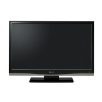
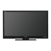
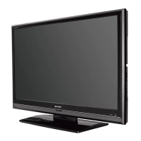
Detailed technical specifications of the LC-42D65U model.

Chapter 2: Operation Manual

Operation Manual

Instructions for operating the TV.

Chapter 3: Dimensions

Dimensions

Physical dimensions of the LC-42D65U television.

Chapter 4: Removing of Major Parts

Removing of Major Parts

Step-by-step guide for disassembling major TV components.

Chapter 5: Adjustment

Adjustment Procedure

Procedures for adjusting TV settings and software upgrades.

Chapter 6: Trouble Shooting Table

Trouble Shooting Table

Diagnostic tables and solutions for common TV issues.

Chapter 7: Major IC Informations

Major IC Informations

Details and functions of key integrated circuits.

Chapter 8: Overall Wiring/Block Diagram

Overall Wiring Diagram

Visual representation of internal wiring connections.

System Block Diagram

Functional block diagram of the TV's internal system.

Chapter 9: Printed Wiring Board Assemblies

Key Unit

Component layout for the Key Unit printed circuit board.

Main Unit

Component layout for the Main Unit printed circuit board.

R/C, LED Unit

Component layout for the R/C and LED Unit printed circuit board.

Chapter 10: Schematic Diagram

Description of Schematic Diagram

Explanations of schematic symbols and measurement conditions.

Key Unit

Detailed schematic for the Key Unit.

Main Unit

Detailed schematics for the Main Unit components.

R/C, LED Unit

Detailed schematic for the R/C and LED Unit.

Parts Guide

Printed Wiring Board Assemblies

List of PWB part numbers and descriptions.

LCD Panel

Part number for the LCD panel assembly.

KEY Unit Parts

List of parts for the KEY Unit (DUNTKE266FM02).

MAIN Unit Parts

List of parts for the MAIN Unit (DUNTKE716FM02).

R/C, LED Unit Parts

List of parts for the R/C and LED Unit (DUNTKE868FM01).

Cabinet and Mechanical Parts

List of cabinet and mechanical components.

Supplied Accessories

List of items included with the TV.

Service Jig

Special tools or cords for servicing.

Related product manuals