LC-42/46/52D85X
5 – 15
10)Mode Fixed [INPUT MODE FIXED]
10. Video signal adjustment procedure
* The adjustment process mode menu is listed in Section 4.
Signal generator level adjustment check (Adjustment to the specified level)
1. Entering the adjustment process mode
Enter the adjustment process mode according to Section 3.
2. RF AGC adjustment
Selection “VARIABLE” or “FIXED” is selectable. (Loop is provided.)
Default VARIABLE
Function When set to “FIXED”, it is disable to switch to other channel or input after start in the set value of “Start Mode (INPUT
MODE START)”.
Keys disabled when not
set to Default (Example)
Channel UP/Down, Direct, Channel Button, FLASHBACK, INPUT, STILL, Digit Select and Direct input switching
Remarks • When “START MODE” is set to “NORMAL”, this item is disable to set. (Automatically set to “VARIABLE”.)
• When set to “FIXED”,
The Channel setting MENU (Menu-setup-Auto Installation, Programme setup and Child Lock item hatching) and
Input Selection MENU in MENU are not displayed.
• Composite signal PAL : 0.7Vp-p ± 0.02Vp-p (Pedestal to white level)
• RGB signal : 0.7Vp-p ± 0.02Vp-p
• 15K component signal (50 Hz) : Y level : 0.7Vp-p ± 0.02Vp-p (Pedestal to white level)
: PB, PR level : 0.7Vp-p ± 0.02Vp-p
Adjustment point Adjustment Conditions Adjustment procedure
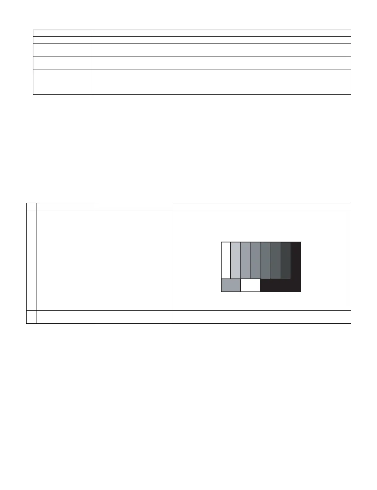
1 Setting [Signal]
PAL
Split Field Colour Bar RF signal
U/V
[Terminal]
TUNER
• Feed the PAL Split Field colour bar signal (E-12ch) to TUNER.
Signal level: 55 dB µV ± 1dB (75Ω LOAD)
2 Auto adjustment
performance
Page 3/32 Bring the cursor on [RF AGC ADJ] and press [ENTER] [RF AGC ADJ OK]
appears when finished.
[E-12CH]
㸡100% white