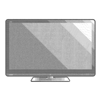
Do you have a question about the Sharp LC-52LE640U and is the answer not in the manual?
Essential safety measures for service technicians to prevent hazards.
Checks to ensure no fire or shock hazard exists before returning the unit.
Guidance on using identical replacement parts for safety and performance.
Lists key PWB units, other units, ICs, and service jigs for the models.
Details on screen size, resolution, TV reception, and audio standards.
Lists available input ports and supported OSD languages.
Information on power consumption, weight, and physical dimensions of the models.
Identifies external controls and connection terminals on the TV.
Explains the purpose and operation of each button on the remote control.
Step-by-step instructions for securely attaching the TV stand.
Detailed measurements for the LC-52LE640U/C6400U models.
Detailed measurements for the LC-60/70LE640U,C6400U models.
Steps for removing stand and rear cabinet for 52-inch models. Also covers 60/70-inch.
Procedures for removing speakers, KEY unit, and metal angles for 52/60-inch models. Also covers 70-inch.
Guidance on safely disconnecting various internal unit connectors across models.
Steps to remove main PWB, LCD control, and power units for 60-inch models. Also covers 70-inch.
Instructions for removing accessory modules like RC, ICON, and WiFi units across models.
Guidelines for proper assembly, ensuring no gaps between cabinet parts.
Guidance on replacing PWB units and ICs, including software updates.
Procedures for upgrading main and monitor microprocessor software via USB.
Steps to access and exit the service adjustment process mode.
How to start, exit, and set values in the public mode.
Method for diagnosing issues based on the center icon LED status.
Details on LED flashing patterns indicating specific error conditions.
Diagnostic steps for no video on Composite, Component, Broadcast, PC, and HDMI inputs.
Diagnostic steps for no audio on HDMI, Digital Audio Output, and monitor speakers.
Details on the HDMI input processor, TMDS cores, and adaptive equalizer.
Description of the main LSI combining video decoding, audio, and a microprocessor.
Function of the microprocessor for system operation and power control.
Information on the Class-D audio amplifier and its output capabilities.
Demodulator for digital terrestrial HDTV and digital CATV signals.
Shows the interconnections between major units and modules in the TV.
Illustrates the functional blocks and data flow within the television system.
List of available PWB assemblies with their part codes and descriptions.
Part numbers for the LCD panel modules for different screen sizes.
Exploded views and part lists for cabinet components of 52, 60, and 70-inch models.
Lists of included accessories and packing materials for 52, 60, and 70-inch models.
Part numbers for specialized jigs used for servicing the units.
| Display diagonal | 52 \ |
|---|---|
| Display brightness | - cd/m² |
| Native aspect ratio | 16:9 |
| Native refresh rate | 120 Hz |
| Supported video modes | 1080p |
| Viewing angle, vertical | 176 ° |
| Contrast ratio (dynamic) | 4000000:1 |
| Supported graphics resolutions | 1920 x 1080 (HD 1080) |
| 3D | No |
| Placement supported | Horizontal |
| Product color | Black |
| Panel mounting interface | - mm |
| Tuner type | Analog & digital |
| Analog signal format system | NTSC |
| Digital signal format system | ATSC |
| RMS rated power | 20 W |
| Number of speakers | 2 |
| HDCP | - |
| HDMI version | 1.4 |
| HDMI ports quantity | 4 |
| USB 2.0 ports quantity | USB 2.0 ports have a data transmission speed of 480 Mbps, and are backwards compatible with USB 1.1 ports. You can connect all kinds of peripheral devices to them. |
| S-Video inputs quantity | 0 |
| Component video (YPbPr/YCbCr) in | 1 |
| AC input voltage | 120 V |
| AC input frequency | 60 Hz |
| Power consumption (standby) | - W |
| Power consumption (typical) | 150 W |
| Sustainability certificates | ENERGY STAR |
| Depth (with stand) | 333 mm |
|---|---|
| Height (with stand) | 771 mm |
| Weight (with stand) | 25500 g |
| Depth (without stand) | 72 mm |
| Width (without stand) | 1208 mm |
| Height (without stand) | 739 mm |
| Weight (without stand) | 22500 g |


 Loading...