LC-65D64U
4 – 1
LC-65D64U
Service Manual
CHAPTER 4. REMOVING OF MAJOR PARTS
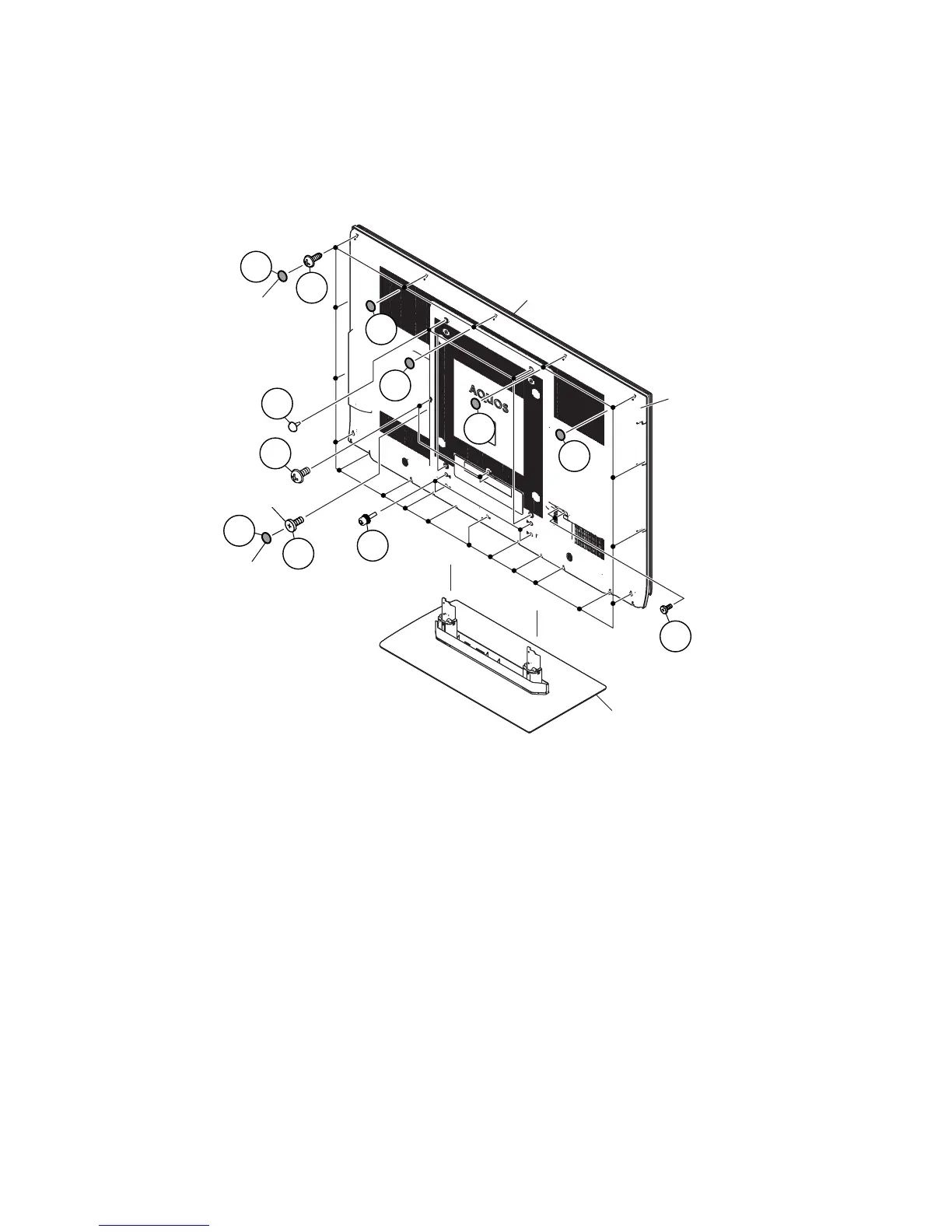
[1] REMOVING OF MAJOR PARTS
1. Remove the 6 black sheets.
2. Remove the 20 lock screws, 1 lock screw, 3 lock screws, 2 lock screws, 4 lock clips and detach the Rear Cabinet.
3. Remove the 4 lock screws and detach the Stand.
CAUTION: In the case of assembly, the new sheet (PSPAKA237WJ00 and PSPAGA386WJ00) can be stuck on these screws.
Front Cabinet
Stand
Rear Cabinet
2
1
1
1
1
1
2
2
2
2
1
3
Black Sheet
Black Sheet
Flat head screw