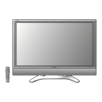
LC-65D90U
SERVICE MANUAL
In the interests of user-safety (Required by safety regulations in some countries) the set should be restored
to its original condition and only parts identical to those specified should be used.
MODEL
LC-65D90U
SHARP CORPORATION
This document has been published to be used for
after sales service only.
The contents are subject to change without notice.
LCD COLOR TELEVISION
CONTENTS
» IMPORTANT SERVICE SAFETY PRECAUTION ........................................................................................2
» SPECIFICATIONS ........................................................................................................................................5
» OPERATION MANUAL .................................................................................................................................6
» DIMENSIONS .............................................................................................................................................12
» REMOVING OF MAJOR PARTS ................................................................................................................13
» ADJUSTMENT PROCEDURE....................................................................................................................18
» TROUBLE SHOOTING TABLE ..................................................................................................................37
» FUNCTIONS OF MAJOR ICs (VIDEO PROCESSOR) ..............................................................................51
» FUNCTIONS OF MAJOR ICs (MONITOR) ................................................................................................54
» OVERALL WIRING DIAGRAM ...................................................................................................................56
» SYSTEM BLOCK DIAGRAM ......................................................................................................................58
» DISPLAY BLOCK DIAGRAM ......................................................................................................................60
» MAIN BLOCK DIAGRAM ............................................................................................................................62
» DIGITAL BLOCK DIAGRAM .......................................................................................................................64
» AV BLOCK DIAGRAM ................................................................................................................................66
» POWER BLOCK DIAGRAM .......................................................................................................................68
» PRINTED WIRING BOARD ASSEMBLIES ................................................................................................70
» REPLACEMENT PARTS LIST..................................................................................................................134
» PACKING OF THE SET ............................................................................................................................203
» SCHEMATIC DIAGRAM .................................................................................................................. D1-D135
Page
SX5P9LC65D90U