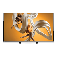
Do you have a question about the Sharp LC-65LE654U and is the answer not in the manual?
Identifies the service manual for the specific LCD TV model.
Details compliance with FCC regulations for digital devices and potential interference.
States compliance with EEC directive for electromagnetic compatibility.
Advises on proper grounding and use of AC power cords.
Lists built-in TV channel selector, HDTV, composite/component, HDMI inputs.
Highlights advanced video functions and power saving features below 0.5W.
Explains user-configurable OSD settings for display, sound, channels, and aspect.
Provides detailed specs for the TFT LCD panel including resolution, size, depth, and pitch.
Lists all available input and output connectors like USB, HDMI, RCA, SPDIF.
Details input voltage, current, power consumption, and speaker output specifications.
Specifies operating temperature, humidity, and altitude limits for the device.
Provides dimensions and weight details for the display module and the unit with base.
Offers crucial precautions for mounting, handling, and avoiding damage to the LCD module.
Describes the status of the front LED indicator (Off/White) and its meaning.
Explains how to operate the TV using the side control buttons like Power and Menu.
Details navigation for channel selection, volume, and input changes within the OSD.
Lists the primary categories available in the TV's On-Screen Display menu.
Lists preset resolution modes for HD video signals received via HDMI.
Lists preset resolution modes for general video inputs.
Provides a detailed pin assignment table for the HDMI connector.
Lists the frequencies associated with different HDMI video signal standards.
Details specifications for RF, AV/Composite, and Component video connectors.
Lists specifications for audio input via RCA and analog audio output.
Details the pinout and signals for the JP1 connector between the power and main boards.
Lists the pinout for the J13 connector linking the main board to the IR receiver board.
Details the JI3 connector pinout for the main board to display board communication.
Provides the pinout for the JA1 connector from the main board to the speaker.
Details the JM4 connector pinout for the main board to the panel interface.
Explains the signal processing routes for HDMI, HDTV, CVBS, TV, and DTV inputs.
Provides a general overview of the RTD2986ID chip's capabilities and integration.
Details RTD2986ID features related to system control, audio processing, and sound effects.
Covers RTD2986ID video decoding, MHL technology support, and mobile device streaming.
Lists RTD2986ID video decoder capabilities including multi-standard support and comb filters.
Details RTD2986ID features for ATV IF demodulation and DTV transport stream processing.
Covers RTD2986ID codec support and video/audio post-processing functions.
Details RTD2986ID image processing features like Smart-Fit, Color-Recover, and Clean-Picture.
Lists RTD2986ID features for panel, memory, peripheral, and high-speed interfaces.
Provides electrical specifications, operating conditions, and absolute maximum ratings.
Provides a general description of the MT29F4G08ABAEAWP flash memory device.
Explains the operation of the asynchronous interface bus for NAND flash data transfer.
Details the enable and standby modes for NAND flash operation and power saving.
Describes asynchronous commands, addresses, and their logic level requirements.
Explains the process of asynchronous data input for NAND flash operations.
Details the procedure for asynchronous data output from NAND flash.
Covers device initialization, write protection, and ready/busy signals.
Explains how to read manufacturer and device ID using the 90h command.
Details the ECh command for reading the ONFI parameter page.
Lists the key features and benefits of the TAS5707L audio amplifier.
Describes the PA136PD MEMC chip, its MotionEngine technology, and applications.
Highlights notable features like MEMC, 2D-to-3D conversion, and local dimming.
Details the advanced MEMC technology, refresh rates, and video processing of PA136PD.
Covers input ports like LVDS and control interfaces, plus the integrated MCU functionality.
Shows the mechanical dimensions and tolerances for the PA136PD 208-pin eLQFP package.
Lists absolute maximum ratings for various supply voltages and temperatures.
Details power supply specifications and DC characteristics for different voltage rails.
Presents waveforms for TMDS signals in 1080i and 1080p HDMI inputs.
Displays waveforms for YCbCr color bar and timing signals for analysis.
Provides troubleshooting steps for problems related to video display.
Offers troubleshooting steps specifically for HDMI input display problems.
Outlines troubleshooting steps for issues related to the DC-DC converter circuits.
Provides troubleshooting steps for problems concerning the audio output.
Presents a high-level block diagram of the TV's system architecture.
Illustrates the power supply tree, showing voltage distribution to system components.
Provides instructions and password for entering the TV's factory service menu.
Details the procedure and password for entering the TV's service menu.
Step-by-step guide on how to prepare and perform a firmware update using a USB flash drive.
Lists spare parts with child P/N, specification, quantity, and circuit number.
Provides a comprehensive list of all components and assemblies with part numbers and circuit references.
Shows the schematic and connections for the TV's on-board control keypad.
Details the circuit diagram for the IR receiver module.
Shows the circuit for the white LED power indicator.
| Screen Size | 65 inches |
|---|---|
| Display Technology | LCD |
| Resolution | 1920 x 1080 |
| Backlight Type | LED |
| Refresh Rate | 60 Hz |
| Smart TV | Yes |
| HDMI Ports | 3 |
| Audio Output | 20 W |
| Built-in Wi-Fi | Yes |
| Bluetooth | No |


