MX-M700N TRANSFER SECTION M – 1
MX-M700N
5GTXKEG/CPWCN
[M] TRANSFER SECTION
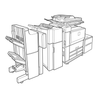
1. Electrical and mechanism relation diagram
Code
Signal
name
Name Function/Operation Type NOTE
DM DM OPC drum motor Drives the OPC drum and the transfer section. DC brushless
motor
TURM TURM Transfer separation motor Drives and separates the transfer belt. DC brush motor The transfer
belt is pressed
on the OPC
drum only
during printing.
THPS2 THPS2 Transfer belt contact/separation
home position sensor 2
Transfer belt separation home position detection 2 Transmission
type
Other sensor,
switch
THV THV Transfer high voltage High voltage for transfer
HUS-TC HUS-TC Process humidity sensor Process section peripheral humidity detection Humidity sensor Analog
detector
(Not used)
No. Name Function/Operation
1 Transfer drive roller (Drive) Drives the transfer belt.
2 Transfer cleaning roller Cleans the transfer belt.
3 Transfer belt Transfers toner images from the OPC drum to paper.
4 Transfer tension roller Applies a proper tension to the transfer belt.
5 Transfer belt discharge brush Connects the transfer belt to the chassis ground.
6 Transfer roller Applies a transfer voltage to the transfer belt.
7 Transfer auxiliary roller (Idle) Helps to stretch the transfer belt.
8 Transfer (TCCL) bias high voltage PWB Generates a bias voltage for the transfer cleaning roller in cleaning or in the print mode.
5
4
3
2
1
12
11
10
9
8
7
6
5
4
3
2
1
13
14
15
16
17
18
PCU
PWB
GND2
/DM
DMCLK
DM-T
S5B-PH-K-S
+5V2
2
1
+38V
B2PS-VH
GND1
B1v8B-PHDSS-B
CN-6
GND2
/DM
DMCLK
DM-T
+5V2
GND2
/DVM
DVMCLK
DVM-T
+5V2
GND2
+5V2
/FUM
FUMCLK
FUM-T
+24V1
GND2
/VFM-BKR
AC PWB
11
10
12
14
15
16
+38V
+38V
GND1
GND1
+38V
GND1
CN-5
B16B-PADSS-1
DM
CN-8
20
19
18
17
16
15
14
13
12
11
10
9
8
7
6
5
4
3
2
1
PCS-LED
PCS
DMS-LED
DMS
/DL
/PTDL
/PSPS
HUS-TC
GND2
TH-CL
GND2
TLS
GND2
B20B-PHDSS-B
(NC)
+24V1
+5V2
+24V1
+12V2
+12V2
+24V-DL
10
9
8
7
MHV-T
/THV+PWM
/CHV-PWM
THV+REM
CN-15
B34B-PHDSS-B
9
8
7
6
THV
HV
CN-1
B16B-PH-K-S
MHV-T
/THV+PWM
/CHV-PWM
THV+REM
FPS-187(WH)
1
2
4
3
1
8
4
5
6
7
3
2
6
24
23
22
21
20
19
18
17
16
15
14
13
12
11
10
1
9
8
7
6
5
4
3
2
25
26
27
28
29
30
31
32
9
8
7
6
5
4
3
2
1
9
8
7
6
5
4
3
2
1
20
19
18
17
16
15
14
13
12
11
10
20
19
18
17
16
15
14
13
12
11
10
24
23
22
21
24
23
22
21
25
26
27
28
29
30
31
32
25
26
27
28
29
30
31
32
B32B-PHDSS-B
+24V1
GND2
+24V1
/RRC
(NC)
+24V(DSW)
+24V1
+5V-APPD1
+5V-APPD2
+5V-PFD2
+5V-DSWD
+5V-AINPD
+5V-THPS1
+5V-THPS2
PFD2
THPS1
THPS2
TURM
/SFM
APPD1
APPD2
AINPD
/CFM-AM1
DSWD
/DGS
(NC)
DSW-L
CN-7
GND2
GND2
(NC)
(NC)
DRAWER
QR/P4-32S-C(01)/QR/P4-32P-C(01)
/CFM-DV
TURM
THPS2
/ADUM2/A
/ADUM2A
/ADUM2B
/ADUM2/B
/ADUM1/A
/ADUM1A
/ADUM1B
/ADUM1/B
+5V-APPD1
+5V-APPD2
+5V-AINPD
GND2
APPD1
APPD2
AINPD
/DGS
+24V2
+24V(DSW)
(NC)
+24V1
GND2
TURM
DSW-L
+5V-PFD2
+5V-THPS2
PFD2
THPS2
/TCB-PWM
DSW-ADU
+5V-DSW
/CFM-ADU
/TCBIAS
LEFT DOOR UNIT
8
7
6
5
4
3
2
1
9
10
11
12
8
7
6
5
4
3
2
1
9
10
11
12
3
2
1
SMR-12V-N/SMP-12V-NC
GND2
179228-3
THPS2
+5V-THPS2
2
1
GND2
PHR-2
TURM
+5V-PFD2
THPS2
PFD2
+5V-THPS2
DSW-L
DSW-L
+24V1
GND2
TURM
/TCB-PWM
/CFM-ADU
/TCBIAS
7
5
4
3
2
1
6
B6B-PH-K-S
DSW-L
DSW-L
GND2
F-GND
/TCB-PWM
Bias
FPS-187
TB PWB
/TCBIAS