36
3.1.3 Installing the Expansion
1/0
Port
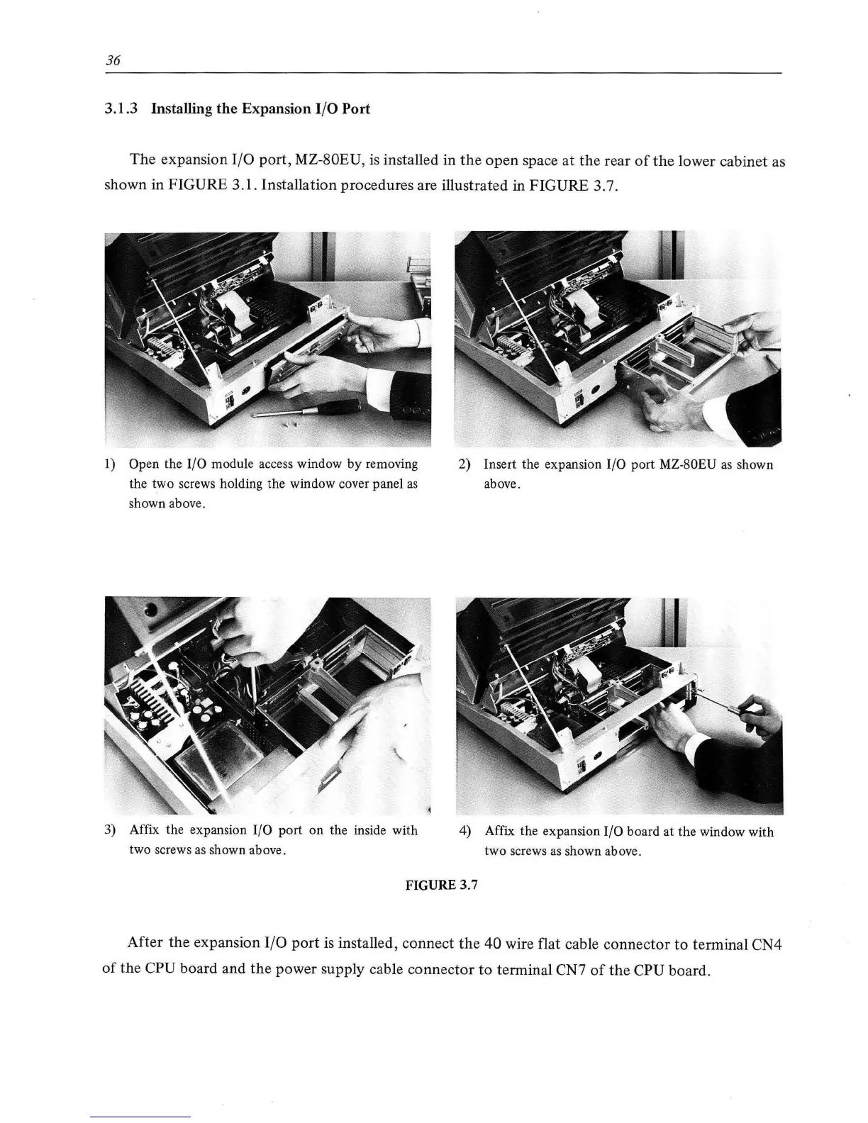
The
expansion
1/0
port, MZ-80EU,
is
installed in
the
open
space at
the
rear
of
the
lower cabinet as
shown in FIGURE 3.
1.
Installation procedures are illustrated
in
FIGURE 3.7.
1)
Open the
I/0
module access window by removing
the two screws holding the window cover panel
as
shown above.
3) Affix the expansion
I/0
port on the inside with
two screws
as
shown above.
2) Insert the expansion
I/0
port MZ-80EU
as
shown
above.
4) Affix the expansion
I/0
board at the window with
two screws as shown above.
FIGURE 3.7
After
the
expansion
1/0
port
is
installed, connect
the
40
wire flat cable connec
tor
to
terminal CN4
of
the
CPU board and
the
power supply cable connector
to
terminal CN7
of
the
CPU board.