85
The
input/output
group
of
instructions in the Z-80A allow for a wide range
of
transfers between external memory
locations or the general purpose
CPU registers, and the external
I/0
devices. In each case, the port number
is
provided
on the lower 8 bits
of
the address bus during any
I/0
transaction. One instruction allows this port number
to
be speci-
fied by the second byte
of
the instruction while other Z-80A instructions allow it
to
be specified
as
the content
of
the
C register. One major advantage
of
using the C register
as
a pointer
to
the
I/0
device
is
that it allows different
I/0
ports
to
share common software driver routines. This
is
not possible when the address
is
part of the
OP
code
if
the routines
are stored in ROM. Another feature
of
these input instructions
is
that they set the
flag
register automatically
so
that
additional operations are not required to determine the state
of
the input data (for example its parity). The Z-80A CPU
includes single instructions
that
can move blocks
of
data (up
to
256 bytes) automatically
to
or from any
I/0
port
directly
to
any memory location. In conjunction with the dual set
of
general purpose registers, these instructions pro-
vide for fast
I/0
block transfer rates. The value
of
this
I/0
instruction set
is
demonstrated by the fact that the Z-80A
CPU
can provide all required floppy disk formatting (i.e., the CPU provides the preamble, address, data and enables the
CRC codes) on double density floppy disk drives on an interrupt driven basis.
Finally, the basic
CPU control instructions allow various options and modes. This group includes instructions such
as
setting or resetting the interrupt enable flip flop or setting the mode
of
interrupt response.
4.2 ADDRESSING MODES
Most
of
the Z-80A instructions operate on data stored in internal CPU registers, external memory or in the
1/0
ports. Addressing refers to how the address
of
this data
is
generated in each instruction. This section
gives
a brief sum-
mary
of
the types
of
addressing used in the Z-80A while subsequent sections detail the type
of
addressing available for
each instruction group.
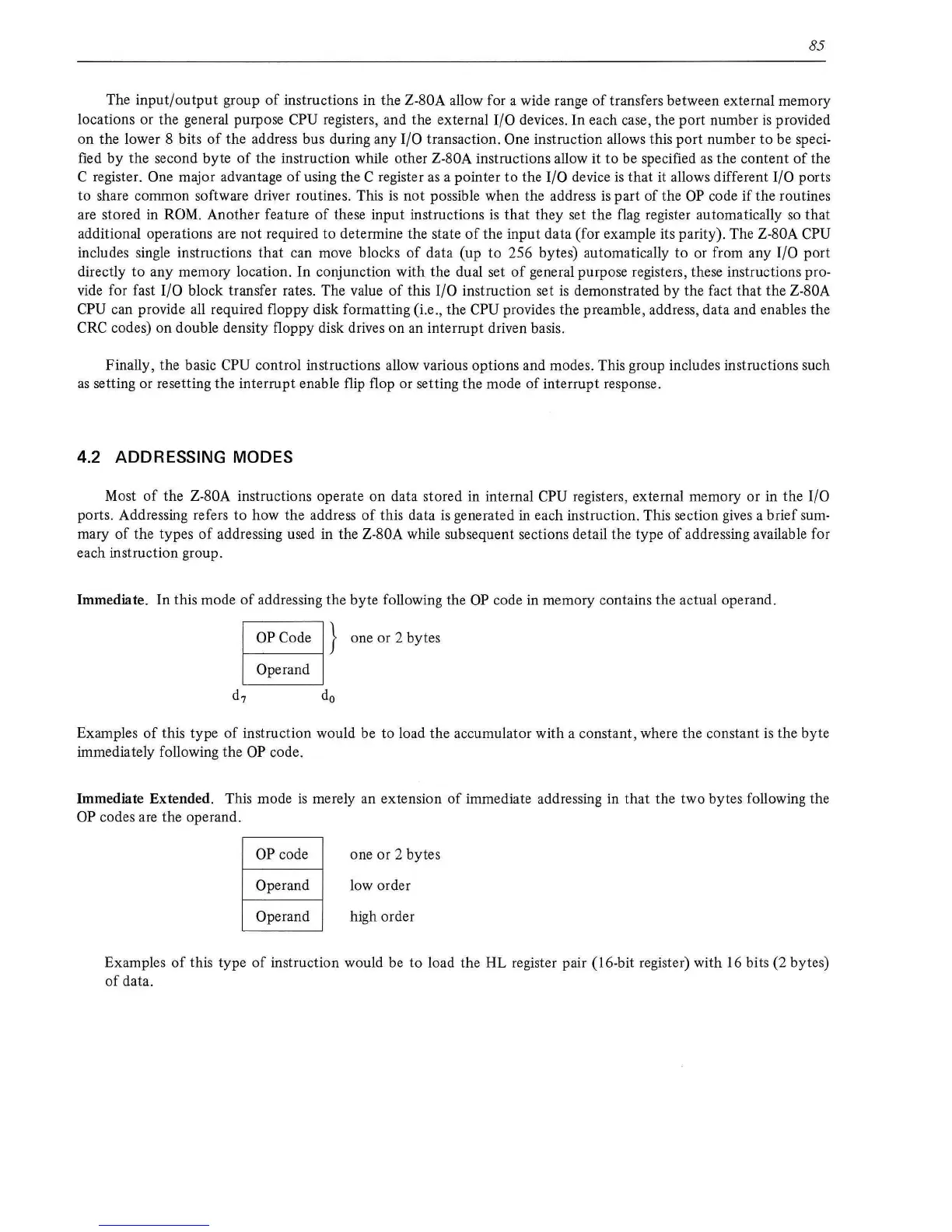
Immediate. In this mode
of
addressing the byte following the
OP
code
in
memory contains the actual operand.
OP
Code } one or 2 bytes
Operand
Examples
of
this type
of
instruction would be to load the accumulator with a constant, where the constant
is
the byte
immediately following the
OP
code.
Immediate Extended. This mode
is
merely an extension
of
immediate addressing in that the two bytes following the
OP
codes are the operand.
OP
code
Operand
Operand
one or 2 bytes
low order
high order
Examples
of
this type
of
instruction would be
to
load the HL register pair (16-bit register) with 16 bits (2 bytes)
of
data.