EasyManua.ls Logo

Sharp PJ-ST161 - User Manual

Sharp PJ-ST161
16 pages
Print Icon
To Next Page IconTo Next Page
Loading...
SHARP SERVICE MANUAL
ELECTRIC FAN
MODEL PJ-ST161
In the interests of user-safety (Required by safety
regulations in some countries) the set should be restore
to its original condition and only parts identical to those
specied should be used.
SHARP CORPORATION
TABLE OF CONTENTS
PARTS IDENTIFICATIONS AND SPECIFIC INFORMATION ................................................
CAUTIONS FOR USE ............................................................................................................
CLEANING AND MAINTENANCE ..........................................................................................
WIRING DIAGRAM AND CIRCUIT DIAGRAM .......................................................................
COMPONENT REPLACEMENT PROCEDURE .....................................................................
TROUBLESHOOTING ............................................................................................................
SERVICE PARTS LIST ...........................................................................................................
Page
2
3
3
4
5 - 10
11
12 - 16

Questions and Answers

Summary

Parts Identification and Specific Information

Parts Identification

Detailed breakdown of fan components with visual references for assembly.

Specific Information

Technical specifications and dimensions of the electric fan, including ratings.

Cautions for Use

Cleaning and Maintenance

Wiring and Circuit Diagrams

Wiring Diagram

Electrical connections and layout for the fan's components, showing wire routing.

Circuit Diagram

Schematic representation of the fan's electrical circuit for troubleshooting purposes.

Component Replacement Procedures - Part 1

Remove Grille Assembly

Step-by-step guide to safely remove the fan grille assembly for access.

Remove Base Assembly

Instructions for detaching and removing the fan's base assembly.

Component Replacement Procedures - Part 2

Remove Bottom Plate

Procedure for disassembling and removing the bottom plate of the fan.

Remove Power Cord

Detailed steps for safely disconnecting and removing the power cord.

Component Replacement Procedures - Part 3

Remove Piano Switch Assembly

Guide to disassembling and removing the fan's piano switch unit.

Component Replacement Procedures - Part 4

Remove Lock Spring Cover

Instructions for detaching and removing the lock spring cover.

Remove Adjustable Housing Assembly

Steps to remove the adjustable housing assembly from the fan.

Component Replacement Procedures - Part 5

Remove Reel Spring

Procedure for safely removing the reel spring component.

Remove Motor Assembly

Detailed instructions for removing the main motor unit.

Component Replacement Procedures - Part 6

Remove Hinge Assembly

Guide to disassembling and removing the fan's hinge assembly.

Troubleshooting

Service Parts List

Overview

This document is a service manual for the SHARP ELECTRIC FAN, model PJ-ST161. It provides comprehensive information for servicing and maintaining the device, including parts identification, specific information, cautions for use, cleaning and maintenance instructions, wiring and circuit diagrams, component replacement procedures, troubleshooting, and a service parts list.

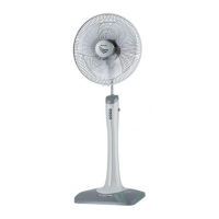
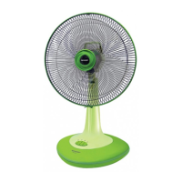
The electric fan is designed to provide cooling by circulating air. It features a stand-type design with an adjustable height and oscillation function to distribute air across a wider area. The fan includes a front grille, rear grille, blade, and a motor assembly, all contributing to its primary function of air movement.

Usage Features:

The fan is operated via a piano switch, which likely controls power and fan speed settings. An adjustable knob allows users to modify the fan's height and angle, providing flexibility in directing airflow. The oscillation function, controlled by a clutch knob on the motor assembly, enables the fan head to sweep from side to side, ensuring broader air distribution. The design includes a fixing lock and grille lock nut for securing the grilles and blade, ensuring safe operation.

Maintenance Features:

The manual outlines detailed procedures for cleaning and maintenance, emphasizing user safety and prolonging the device's lifespan.

  • Cleaning:

    • Blade, Front Grille, and Rear Grille: These components should be disassembled, wiped with a damp cloth mixed with a cleaning agent, and then dried.
    • Body: The main body of the fan can be cleaned with a damp cloth using water or a mild soapy liquid.
    • Important Cleaning Remarks: It is crucial not to wet any electric parts or the motor. Chemical substances, thinner, or kerosene should not be used for cleaning, as they can damage the surface or shape of the unit.
  • Component Replacement Procedures: The manual provides step-by-step instructions for disassembling and reassembling various parts, which is essential for maintenance and repair. These procedures include:

    • Removal of Grille Assembly: This involves unlocking the fixing lock, pulling the front grille, turning the spinner fan clockwise to remove the blade, and turning the grille lock nut counterclockwise to remove the rear grille.
    • Removal of Base Assembly: This requires removing screws holding the base assembly and detaching it from the unit.
    • Removal of Bottom Plate: After removing the base assembly, screws holding the bottom plate are removed to free it.
    • Removal of Power Cord: This is a more involved process, requiring the removal of the base assembly, body cover, separating the front and back bodies, removing screws and cutting cord bands holding the power cord, and finally cutting the power cord lead wire from the piano switch assembly.
    • Removal of Piano Switch Assembly: This involves removing the power cord, cutting lead wires from the piano switch assembly, removing screws, detaching the knob switch, and removing the insulation sheet.
    • Removal of Lock Spring Cover: This procedure follows the removal of the base assembly, body cover, separation of front and back bodies, removal of lead wire motor screws, cutting cord bands, removing closed terminals, cutting power cord motor from the piano switch assembly, and removing screws holding the adjustable housing assembly.
    • Removal of Adjustable Housing Assembly: This involves removing the lock spring cover and then detaching the adjustable housing assembly from the adjustable tube.
    • Removal of Reel Spring: After removing the lock spring cover, the screw holding the reel spring is removed.
    • Removal of Motor Assembly: This extensive procedure involves removing the grille assembly, screws holding the motor bracket, screws holding the motor cover, pulling the clutch knob, removing screws holding the link rod, and removing the screw holding the motor assembly to the hinge assembly.
    • Removal of Hinge Assembly: This final removal step involves removing the motor assembly, screws holding the hinge assembly to the neck, and the screw holding the link rod to the turning axle.

Cautions for Use:

The manual stresses several safety precautions to prevent accidents, electric shock, fire, and damage to the unit:

  • Professional Repair: Users should not disassemble or repair the fan themselves; a qualified dealer should be consulted.
  • Power Cord Safety: A broken power cord must be replaced by the manufacturer, appointed service providers, or equivalent professionals.
  • Unplugging: Always unplug the fan before cleaning or when not in use.
  • Water Immersion: Do not immerse the fan in water or sprinkle water on it to avoid short circuits or equipment damage.
  • Foreign Objects: Never insert fingers or objects through the grille while the blade is rotating.
  • Chemical Sprays: Do not spray vapor or chemicals on the fan while the blade is rotating.
  • Plug Connection: Ensure the plug is tightly inserted to prevent overheating, melting plastic, and conflagration. When unplugging, hold the plug itself, not the cable, to prevent damage.
  • Wet Hands: Do not plug in with wet hands to prevent electric shock.
  • Shared Receptacles: Avoid plugging other appliances into the same receptacle as the fan to prevent overheating and conflagration.
  • Placement: Keep the fan away from curtains, mosquito nets, or objects that could be pulled into the motor, which could cause accidents and damage. Avoid using the fan in high-temperature or high-humidity areas, or on hot or sloped floors, as this can damage the unit.

Troubleshooting:

A dedicated section provides common problems, possible causes, and corrective actions, enabling users or technicians to diagnose and fix issues such as:

  • Fan not operating (e.g., motor failure, faulty connection, coil stator shock, bush friction, fuse deficiency).
  • Motor noise (e.g., loose screws, rotor jam, loose bush).
  • Fan not oscillating (e.g., faulty gear box, tight link rod screws).
  • Fan tilt not adjusting (e.g., hinge spring issues, tight hinge assembly screws).
  • Blade rotation friction (e.g., bush wear, rust on bush axis).
  • Switch button not switching off (e.g., contact switch issues, faulty connector lead wire).
  • Inability to adjust fan height (e.g., reel spring failure, distorted adjustable tube).

This comprehensive manual ensures that the SHARP ELECTRIC FAN PJ-ST161 can be safely used, maintained, and repaired, maximizing its operational life and user satisfaction.

Sharp PJ-ST161 Specifications

General IconGeneral
ModelPJ-ST161
CategoryFan
TypeStand Fan
Blade Size16 inches
Number of Speed Settings3
OscillationYes
Power Consumption50W
Voltage220-240V
Frequency50Hz
Height AdjustmentYes
Tilt AdjustmentYes

Related product manuals