R969(W)
8 – 4
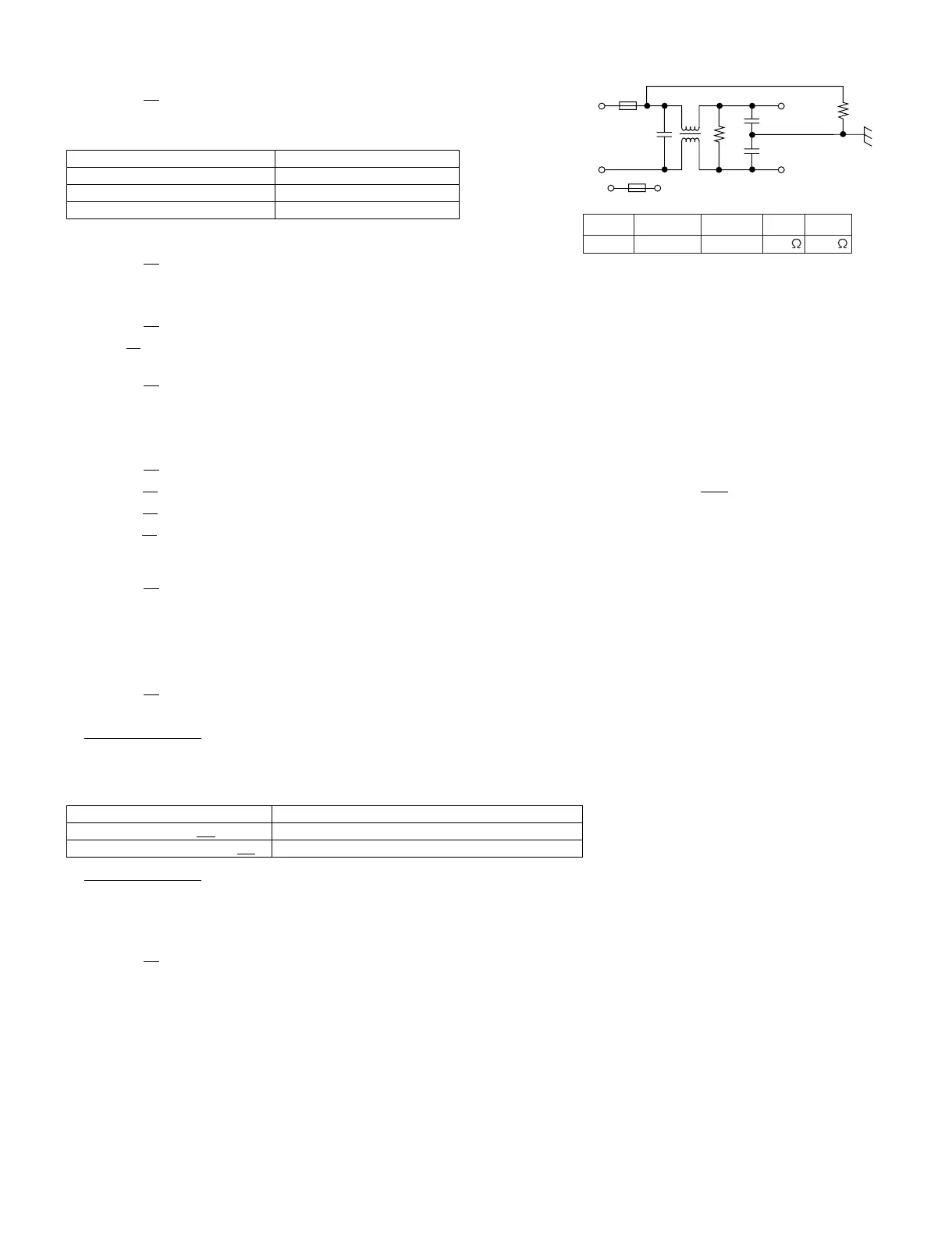
[9] Procedure I: NOISE FILTER TEST
CARRY OUT 3D CHECKS.
Disconnect the leads from the terminals of the noise filter. Using an ohmmeter, check
between the terminals as described in the following table.
If incorrect readings are obtained, replace the noise filter unit.
CARRY OUT 4R
CHECKS.
[10] Procedure J: BLOWN FUSE (F1) 20A
CARRY OUT 3D CHECKS.
If the fuse F1
20A is blown, there is a shorts or grounds in electrical parts or wire harness. Check them and replace the defective parts or repair the
wire harness.
CARRY OUT 4R
CHECKS.
CAUTION: Only replace fuse with the correct value replacement.
[11] Procedure K: BLOWN FUSE (F2) 8A (NOISE FILTER)
CARRY OUT 3D CHECKS.
1. If the fuse F2
F8A is blown when the door is opened, check the monitored latch switch SW1 and monitor switch SW3.
2. If the fuse F2
F8A is blown by incorrect door switching replace the defective switch(es) and the noise filter.
3. If the fuse F2
F8A is blown, there could be shorts in the asymmetric rectifier or there is a ground in wire harness. A short in the asymmetric rectifier
may be occurred due to short or ground in H.V. rectifier, magnetron, high voltage transformer or H.V. wire. Check them and replace the defective
parts or repair the wire harness.
CARRY OUT 4R
CHECKS.
CAUTION: REPLACE NOISE FILTER.
[12] Procedure L: GRILL HEATING ELEMENTS (TOP) AND CONVECTION HEATING ELE-
MENT TEST
CARRY OUT 3D CHECKS.
Before carrying out the following tests make sure the heating element is cool completely.
1. Resistance of heater.
Disconnect the wire leads to the heating element to be tested. Using ohmmeter with low resistance range. Check the resistance across the termi-
nals of the heating element as described in the following table.
2. Insulation resistance.
Disconnect the wire leads to the heating element to be tested. Check the insulation resistance between the element terminal and cavity using a
500V - 100MΩ insulation tester. The insulation resistance should be more than 10 MΩ in the cold start.
If the results of above test 1 and/or 2 are out of above specifications, the heating element is probably faulty and should be replaced.
CARRY OUT 4R
CHECKS.
[13] Procedure M: CONTROL PANEL ASSEMBLY TEST
The touch control panel consists of circuits including semiconductors such as LSI, ICs, etc. Therefore, unlike conventional microwave ovens, proper
maintenance can not be performed with only a voltmeter and ohmmeter.
In this service manual, the touch control panel assembly is divided into two units, Control Unit and Key Unit, and also the Control unit is divided into
two units, CPU unit and Power unit, and troubleshooting by replacement is described according to the symptoms indicated.
1. Key Unit Note: Check key unit ribbon connection before replacement.
The following symptoms indicate a defective key unit. Replace the key unit.
1) When touching the pads, a certain pad produces no signal at all.
2) When touching a number pad, two figures or more are displayed.
MEASURING POINT INDICATION OF OHMMETER
Between N and L Approx. 680 kΩ
Between terminal N and WHITE Short circuit
Between terminal L and RED Short circuit
Table: Resistance of heater
Parts name Resistance
Grill heating elements GH
(Top) Approximately 37.4 Ω -39.7Ω [(18.7Ω - 19.85Ω) x 2 ]
Convection heating elements CH
Approximately 34.09 Ω - 36.72Ω
F2: F8A
20A
WHT
RED
R1
R2
N
Cx
Cy
L
L
L
L (min) Cx ± 20% Cy ± 20% R1 R2
1.0mH 0.22 uF 4700pF 10 M 680k