R969(W)
8 – 5
3) When touching the pads, sometimes a pad produces no signal.
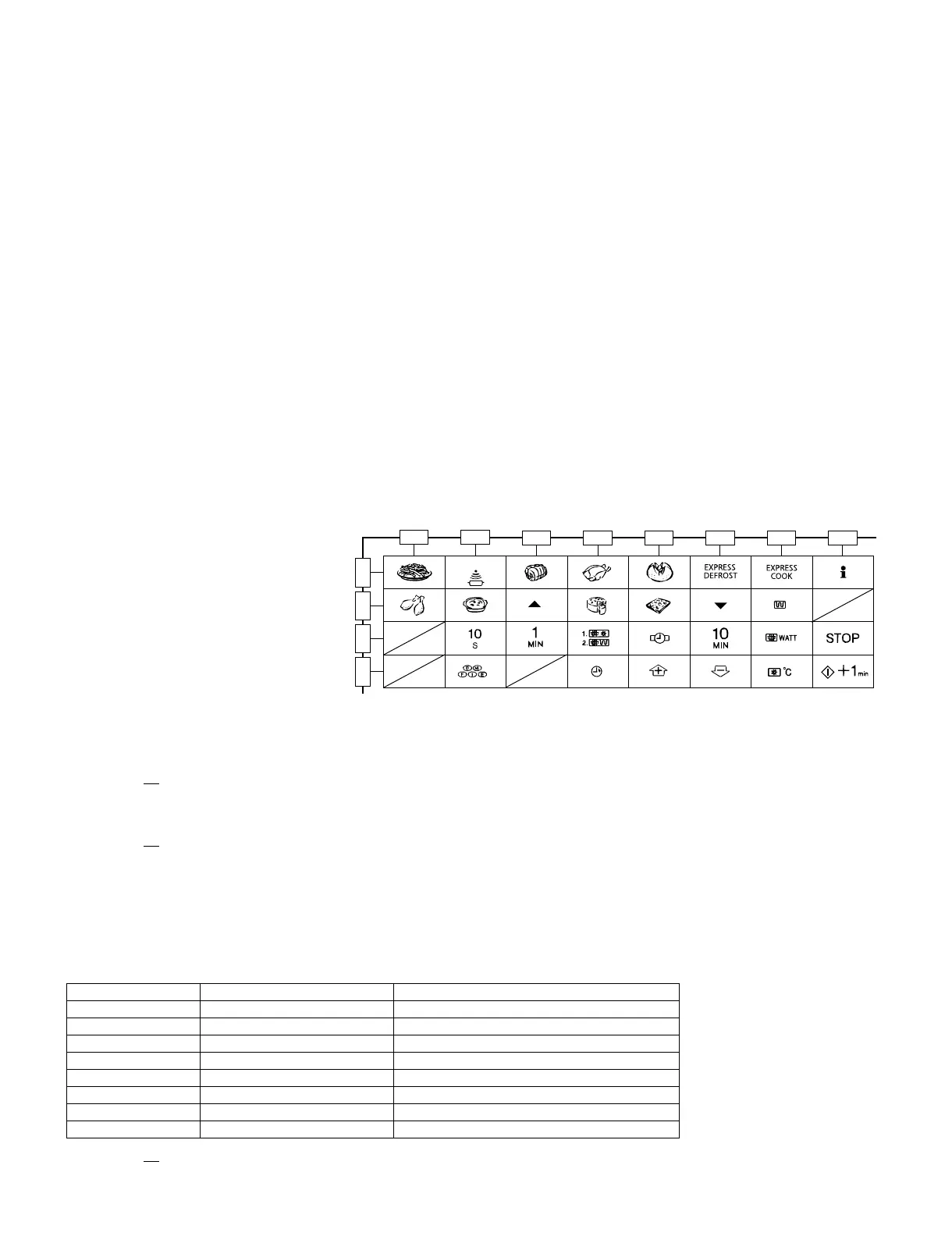
2. Control Panel
The following symptoms indicate a defective control unit. Before replacing the control unit perform the key unit test (Procedure N) to determine if
control unit is faulty.
1) In connection with pads
a) When touching the pads, a certain group of pads do not produce a signal.
b) When touching the pads, no pads produce a signal.
2) In connection with indicators
a) At a certain digit, all or some segments do not light up.
b) At a certain digit, brightness is low.
c) Only one indicator does not light up.
d) The corresponding segments of all digits do not light up; or they continue to light up.
e) Wrong figure appears.
f) A certain group of indicators do not light up.
g) The figure of all digits flicker.
3) 2-3 Other possible troubles caused by defective control unit.
a) Buzzer does not sound or continues to sound.
b) Clock does not operate properly.
c) Cooking is not possible.
d) Proper temperature measurement is not obtained.
[14] Procedure N: KEY UNIT TEST
If the display fails to clear when the STOP pad
is depressed, first verify the flat ribbon cable is
marking good contact, verify that the door sens-
ing switch (stop switch) operates properly; that
is the contacts are closed when the door is
closed and open when the door is open. If the
door sensing switch (stop switch) is good, dis-
connect the flat ribbon cable that connects the
key unit to the control unit and make sure the
door sensing switch is closed (either close the
door or short the door sensing switch connec-
tor). Use the Key unit matrix indicated on the
control panel schematic and place a jumper wire between the pins that correspond to the STOP pad marking momentary contact. If the control unit
responds by clearing with a beep the key unit is faulty and must be replaced. If the control unit does not respond, it is faulty and must be replaced. If
a specific pad does not respond, the above method may be used (after clearing the control unit) to determine if the control unit or key pad is at fault.
CARRY OUT 4R
CHECKS.
[15] Procedure O: RELAY TEST
CARRY OUT 3D CHECKS.
Remove the outer case and check voltage between Pin Nos. 1 and 3 of the 4 pin connector (E) on the control unit with an A.C. voltmeter. The meter
should indicate 230 volts, if not check oven circuit.
Relay Test
Check voltage at the relay coil with a D.C. voltmeter during the microwave cooking operation, grill operation, convection operation or dual operation.
DC. voltage indicated ................................... Defective relay.
DC. voltage not indicated ............................. Check diode which is connected to the relay coil. If diode is good, control unit is defective.
CARRY OUT 4R
CHECKS.
RELAY SYMBOL OPERATIONAL VOLTAGE CONNECTED COMPONENTS
RY1 APPROX. 18.0V D.C. Oven lamp / Turntable motor
RY2 APPROX. 18.0V D.C. High voltage transformer
RY3 APPROX. 24.0V D.C. Grill (Top) heating element
RY4 APPROX. 24.0V D.C. Convection heating element
RY5 APPROX. 24.0V D.C. Fan motor
RY6 APPROX. 24.0V D.C. Touch control transformer
RY7 APPROX. 24.0V D.C. Convection motor
RY8 APPROX. 24.0V D.C. Damper motor
G12 G11 G10 G9
G8 G7
SENSOR COOK
G6 G5 G4 G3 G2 G1