R969(W)
9 – 2
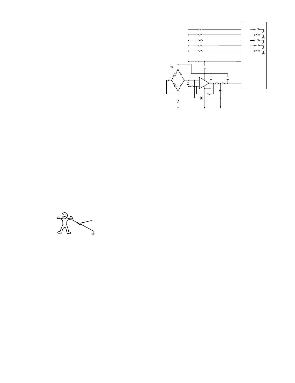
3. Detector Circuit of Absolute Humidity Sensor Cir-
cuit
This detector circuit is used to detect the output voltage of the absolute
humidity circuit to allow the LSI to control sensor cooking of the unit.
When the unit is set in the sensor cooking mode, 16 seconds clearing
cycle occurs than the detector circuit starts to function and the LSI
observes the initial voltage available at its AN1 terminal. With this volt-
age given, the switches SW1 to SW5 in the LSI are turned on in such a
way as to change the resistance values in parallel with R97 — R102.
Changing the resistance values results in that there is the same poten-
tial at both F-3 terminal of the absolute humidity sensor and AN0 termi-
nal of the LSI. The voltage of AN1 terminal will indicate about -2.5V.
This initial balancing is set up about 16 seconds after the unit is put in
the Sensor Cooking mode. As the sensor cooking proceeds, the food
is heated to generate moisture by which the resistance balance of the
bridge circuit is deviated to increase the voltage available at AN1 ter-
minal of the LSI. Then the LSI observes that voltage at AN1 terminal
and compares it with its initial value, and when the comparison
Absolute humidity sensor circuit
[3] SERVICING FOR TOUCH CONTROL PANEL
1. Precautions for Handling Electronic Components
This unit uses CMOS LSI in the integral part of the circuits. When han-
dling these parts, the following precautions should be strictly followed.
CMOS LSI have extremely high impedance at its input and output ter-
minals. For this reason, it is easily influenced by the surrounding high
voltage power source, static electricity charge in clothes, etc., and
sometimes it is not fully protected by the built-in protection circuit.
In order to protect CMOS LSI.
1) When storing and transporting, thoroughly wrap them in aluminium
foil. Also wrap PW boards containing them in aluminium foil.
2) When soldering, ground the technician as shown in the figure and
use grounded soldering iron and work table.
2. Servicing of Touch Control Panel
We describe the procedures to permit servicing of the touch control
panel of the microwave oven and the precautions you must take when
doing so. To perform the servicing, power to the touch control panel is
available either from the power line of the oven itself or from an exter-
nal power source.
1. Servicing the touch control panel with power supply of the
oven:
CAUTION: THE HIGH VOLTAGE TRANSFORMER OF THE MICRO-
WAVE OVEN IS STILL LIVE DURING SERVICING AND
PRESENTS A HAZARD.
Therefore, before checking the performance of the touch control
panel,
1) Disconnect the power supply cord, and then remove outer case.
2) Open the door and block it open.
3) Discharge high voltage capacitor.
4) Disconnect the leads to the primary of the power transformer.
5) Ensure that these leads remain isolated from other components
and oven chassis by using insulation tape.
6) After that procedure, re-connect the power supply cord.
After checking the performance of the touch control panel,
1) Disconnect the power supply cord.
2) Open the door and block it open.
3) Re-connect the leads to the primary of the power transformer.
4) Re-install the outer case (cabinet).
5) Re-connect the power supply cord after the outer case is installed.
6) Run the oven and check all functions.
a) On some models, the power supply cord between the touch
control panel and the oven itself is so short that the two can't be
separated. For those models, check and repair all the controls
(sensor-related ones included) of the touch control panel while
keeping it connected to the oven.
b) On some models, the power supply cord between the touch
control panel and the oven proper is long enough that they may
be separated from each other. For those models, therefore, it is
possible to check and repair the controls of the touch control
panel while keeping it apart from the oven proper; in this case
you must short both ends of the door sensing switch (on PWB)
of the touch control panel with a jumper, which brings about an
operational state that is equivalent to the oven door being
closed. As for the sensor-related controls of the touch control
panel, checking them is possible if the dummy resistor(s) with
resistance equal to that of the controls are used.
2. Servicing the touch control panel with power supply from an
external power source:
Disconnect the touch control panel completely from the oven
proper, and short both ends of the door sensing switch (on PWB) of
the touch control panel, which brings about an operational state
that is equivalent to the oven door being closed. Connect an exter-
nal power source to the power input terminal of the touch control
panel, then it is possible to check and repair the controls of the
touch control panel; it is also possible to check the sensor-related
controls of the touch control panel by using the dummy resistor(s).
3. Servicing Tools
Tools required to service the touch control panel assembly.
1) Soldering iron: 60W
(It is recommended to use a soldering iron with a grounding termi-
nal.)
2) Oscilloscope: Single beam, frequency range: DC - 10MHz type or
more advanced model.
SW1
SW2
SW3
SW4
SW5
P54
P53
P52
P51
P50
LSI
(IC1)
AN0
AN1
620k
300k
150k
75k
37.4k
13
16
17
1
5
8
7
46
80
15
14
47k
47k
IC2
10k
0.01uF
0.015uF
0.01uF
+
VA : -15V
VA : -15V
R90
C90
C
91
C93
C
92
S
F-2
1.8k
F-1
F-3
C
3.57k
3.32k
VC : -5V
0.1
uF
C. Thermistor in
closed vessel
S. Thermistor in
open vessel
R98
R99
R96
R91
360k
R93
R92
R94
R95
R100
R101
R102
R97
approx. 1M ohm