EasyManua.ls Logo

Sharp RP-107H User Manual

Sharp RP-107H
50 pages
To Next Page IconTo Next Page
Page #1 background imageLoading...
Page #1 background image
SHARP
RP-107H/117H
CAS
=o
|
&
SERVICE
MANUAL
/
SERVICE-ANLEITUNG/MANUEL
DE
SERVICE
@
APMS
Automatic
Programmable
Music
Selector
INDEX
TO
CONTENTS
©
SPECIFICATIONS
.......
iy
Re
TS
2-4
NAMES
OF
PARTS
........---+++055
2-4
DISASSEMBLY...
.........
002000
5-8
BLOCK
DIAGRAM.
.....
2.0.2.0
eee
eae
9
CIRCUIT
DESCRIPTION..........-..
10
37
ADJUSTMENT
OF
CIRCUIT.
.........
38
43
BLOCK
DIAGRAM
OF
IC...
0.6...
ee
eee
44
PACKING
METHOD
AND
CAUTION
(UK
ONLY).
0...
.
eee
eee
45
WIRING
SIDE
OF
P.W.
BOARD
(1/2)...
...
47,48
SCHEMATIC
DIAGRAM
(1/2).........-
49,50
WIRING
SIDE
OF
P.W.
BOARD
(2/2).
.....
51,52
SCHEMATIC
DIAGRAM
(2/2).
.........
53,54
CABINET
EXPLODED
TOP
VIEW.
.........
55
CABINET
EXPLODED
BOTTOM
VIEW
......
56
REPLACEMENT
PARTS
LIST.........
57
62
FEATURES
-
BOTH
SIDES
PLAY
+
REPEATED
PLAY
+
APSS
(AUTO
PROGRAM
SEARCH
SYSTEM)
*
APMS
(AUTOMATIC
PROGRAMMABLE
MUSIC
SELECTOR)
+
LARGE,
EASY
TO
READ
INDICATORS
+
FRONT
LOADING
RECORD
COMPARTMENT
*
SYNCHRONIZED
RECORDING
(RP-107H
ONLY)
*
CARTRIDGE
INDICATOR
*
AUTOMATIC
FUNCTION
SYSTEM
ATSM383025PLY
RP-107H
RP-117H
foci
:
eln
the
interests
of
used.
user-safety
the
set
should
be
restored
to
its
original
condition
and
only
parts
identical
to
those
specified
be
@lm
Interesse
der
Benutzer-Sicherheit
sollte
dieses
Geraét
wieder
auf
seinen
ursprunglichen
Zustand
eingestellt
und
nur
die
vorgeschrie-
benen
Teile
verwendet
werden.
e
Dans
I‘intérét
de
la
sécurité
de
l'utilisateur,
l'appareil
devra
étre
reconstitué
dans
sa
condition
premiére
et
seules
des
piéces
identi-
L
ques
a
celles
spécifiées,
doivent
étre
utilisées.
INHALTSVERZEICHNIS
©
TECHNISCHE
DATEN
..............
2-4
TEILEBEZEICHNUNG
..............
2-4
ZERLEGEN...
0.2.2
eee
5-8
BLOCKSCHALTPLAN.............---..
9
SCHALTUNGSBESCHREIBUNG
.......
10
37
EINSTELLUNG
DES
PLATTENSPIELER-
MECHAMISMUS
............-.-.-
38
43
BLOCKSCHALTPLAN
DES
INTEGRIERTEN
SCHALTKREISES................0..
44
VERDRAHTUNGSSE!TE
DER
LEITER-
PLATTE
(1/2)
2.0...
ce
eee
47,48
SCHEMATISCHER
SCHALTPLAN
(1/2).
. .
.49,
50
VERDRAHTUNGSSEITE
DER
LEITER-
PLATTE
(2/2)...
2.222.
.eeeeeee
51,52
SCHEMATISCHER
SCHALTPLAN
(2/2).
.
.
.53,
54
EXPLOSIONSDARSTELLUNG
DES
GEHAUSES
(DRAUFSICHT)
...............000.-
55
EXPLOSIONSDARSTELLUNG
DES
GEHAUSES
(UNTERANSICHT)
............-....
56
ERSATZTEILLISTE...............
57
62
EIGENSCHAFTEN
+
ABSPIELEN
BEIDER
SEITEN
+:
WIEDERHOLTES
ABSPIELEN
+
APSS
(AUTOMATISCHES
PROGRAMMSUCH-
SYSTEM)
+
APMS
(AUTOMATISCHE
PROGRAMMIERBARE
MUSIKWAHL)
+
GROSSE,
LEICHT
ABLESBARE
ANZEIGEN
+
VON
VORN
ZU
BEDIENENDES
SCHALLPLATTEN-
FACH
+
SYNCHRONISIERTE
AUFNAHMEN
*
TONABNEHMERSYSTEM-ANZEIGE
+
AUTOMATISCHES
FUNKTIONSWAHL-SYSTEM
©
TABLE
DES
MATIERES
CARACTERISTIQUES
..............
2-4
NOMENCLATURE.
.............-05
2-4
DEMONTAGE
...........,.000004
5-8
DIAGRAMME
SYNOPTIQUE
.............
9
DESCRIPTION
DU
CIRCUIT..........
10
37
REGLAGE
DU
MECANISME
DE
LECTURE.
38
43
DIAGRAMME
SYNOPTIQUE
DUIC........
44
COTE
CABLAGE
DE
LA
PLAQUETTE
DU
MONTAGE
IMPRIME
(1/2)...........
47,48
DIAGRAMME
SCHEMATIQUE
(1/2)...
..
.49,50
COTE
CABLAGE
DU
LA
PLAQUETTE
DU
MONTAGE
IMPRIME
(2/2),..........
51,52
DIAGRAMME
SCHEMATIQUE
(2/2).
.....
53,
54
VUE
EN
ECLATE
DU
COFFRET
SUPERI-
BUG
gs
ot
4
eth
ak,
tee
oR
We
eee
oes
55
VUE
EN
ECLATE
DU
COFFRET
INFERI-
Sh
ee
ere
eee
ere
ee
eee
©
ee
56
LISTE
DES
PIECES
DE
RECHANGE.....
57
—62
PARTICULARITES
+
LECTURE
DES
DEUX
FACES
+
LECTURE
PAR
REPETITION
+
APSS
(SYSTEME
DE
RECHERCHE
AUTOMATIQUE
DES
PROGRAMMES)
;
+
APMS
(SELECTEUR
PROGRAMMABLE
AUTO.
MATIQUE
DE
MUSIQUE)
+
GRANDS
TEMOINS
FACILES
A
LIRE
+
COMPARTIMENT
DU
DISQUE
A
CHARGEMENT
AVANT
+
ENREGISTREMENT
SYNCHRONISE
*
TEMOIN
DE
LA
CELLULE
*
SYSTEME
A
FONCTION
AUTOMATIQUE
SHARP
CORPORATION
OSAKA,
JAPAN
Question and Answer IconNeed help?

Do you have a question about the Sharp RP-107H and is the answer not in the manual?

Sharp RP-107H Specifications

General IconGeneral
MotorDC servo motor
Signal to noise ratio60dB
Overhang15mm
Signal-to-Noise Ratio60dB
Speeds33, 45 rpm
TonearmStatic balance type
CartridgeMoving magnet type
Output2.5 mV
Frequency Response20Hz to 20kHz
Cartridge weight range4 - 6 g
Dimensions430 x 130 x 375mm

Summary

SPECIFICATIONS

GENERAL

Provides basic operational and electrical specifications for the unit.

TONEARM

Details specifications related to the tonearm assembly and tracking.

CARTRIDGE

Lists specifications for the cartridge and stylus, including frequency response.

TURNTABLE

Outlines specifications for the turntable mechanism and motor type.

NAMES OF PARTS

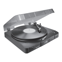
Identifies and labels the various physical components of the unit.

DISASSEMBLY

REMOVAL OF CABINET

Step-by-step guide for removing the main external cabinet.

REMOVAL OF TURNTABLE COVER AND OPERATION PANEL

Instructions for detaching the turntable cover and control panel.

REMOVAL OF FRONT FRAME

Procedure for removing the front frame assembly.

REMOVAL OF INDIVIDUAL P.W.B.s

Guidance on safely removing individual printed circuit boards.

CIRCUIT DESCRIPTION

KEY CONTROL SECTION

Explains the function and operation of the unit's various control keys.

SENSOR SECTION

Details the types and functions of sensors used for detecting disc and tonearm status.

SYNCHRO OPERATION CONTROL SECTION

Describes the control logic for synchronized recording operations.

TURNTABLE MOTOR CONTROL SELECTION

Explains how the microcomputer controls turntable motor open/close functions.

TONEARM CONTROL SECTION

Details the microcomputer's control signals for tonearm movement.

PHONO MOTOR CONTROL SECTION

Explains microcomputer control for phono motor direction and speed.

MUTING

Describes the circuit condition that activates the muting function.

PLAYER CONTROL OPERATION

Outlines how the microcomputer manages player operations upon power-on.

TURNTABLE CHASSIS OPEN OPERATION

Describes the process and conditions for opening the turntable chassis.

TURNTABLE CHASSIS CLOSE OPERATION

Details the process and conditions for closing the turntable chassis.

AUTOMATIC PLAY START OPERATION

Explains how automatic playback is initiated after chassis closure.

PLAYER CONTROL OPERATION TABLE

Provides a table detailing player control sequence based on various inputs.

AUDIO SIGNAL DETECTOR CIRCUIT

Explains the circuit that detects audio signal start/end for muting control.

PROGRAM SPACE DETECTOR CIRCUIT

Describes the circuit for detecting program gaps on a record.

PHONO MOTOR CONTROL CIRCUIT

Explains the circuit controlling the phono motor speed and direction.

INDICATOR DRIVE CIRCUIT

Details the circuit responsible for lighting up various unit indicators.

INPUT/OUTPUT PINS OF MICROCOMPUTER

Microcomputer Pin Assignments

Lists and defines the input/output functions of the microcomputer pins.

SYNCRO RECORDING CONTROL CIRCUIT (RP-107H only)

ADJUSTMENT OF CIRCUIT

TONEARM TRACKING ADJUSTMENT

Guides on adjusting the tonearm for proper tracking accuracy.

TONEARM POSITION INDICATOR ADJUSTMENT

Instructions for calibrating the tonearm position sensor.

SIDE A/SIDE B TONEARM LEAD-IN POSITION

Procedure for setting the correct tonearm entry point for record sides.

APSS SENSOR POSITION ADJUSTMENT

Steps for adjusting the APSS sensor for accurate program detection.

PHONO MOTOR ROTATIONAL SPEED ADJUSTMENT

Instructions on how to adjust the phono motor speed using a strobe viewer.

APSS SENSOR SENSITIVITY ADJUSTMENT

Guidance on adjusting the APSS sensor's sensitivity level.

PACKING METHOD (UK ONLY)

NOTES ON SCHEMATIC DIAGRAM

WIRING SIDE OF P.W. BOARD (1/2)

SCHEMATIC DIAGRAM (1/2)

WIRING SIDE OF P.W. BOARD (2/2)

SCHEMATIC DIAGRAM (2/2)

REPLACEMENT PARTS LIST

DIFFERENCE BETWEEN RP-107H AND RP-107HB

Related product manuals