Do you have a question about the Sharp RP-117 and is the answer not in the manual?
Disconnect power/audio leads and remove any records from the player.
Remove screws from the back and then detach the back and top units.
Open the tray, remove the gear enclosure, and detach microswitch/plate screws.
Remove screws holding the motor plate and examine the gear plate components.
Slip the new cog onto the bush with a 2mm gap from the plate.
Re-attach microswitches and the motor, ensuring correct gear engagement.
Replace covers, plug in, and test the drawer mechanism operation.
Ensure no exposed conductors when testing; do not fit covers with power connected.
This document outlines the procedure for replacing the turntable loading tray gear in Sharp RP-117, RP-107, and RP-119 record players. It serves as a guide for qualified service technicians to perform the necessary repairs.
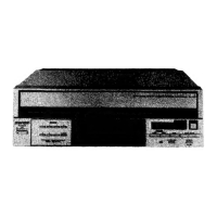
The Sharp RP-117, RP-107, and RP-119 are record players designed to play vinyl records. A key component of these devices is the turntable loading tray, which facilitates the placement and removal of records. The loading tray mechanism relies on a gear system to operate smoothly, allowing the tray to extend and retract as needed. This guide specifically addresses the replacement of a critical gear within this loading mechanism, ensuring the proper functioning of the record player's tray system.
The primary usage feature of these record players is their ability to play vinyl records. Users would typically place a record onto the turntable via the loading tray, and the device would then play the audio. The loading tray is an integral part of the user experience, as it allows for convenient and safe handling of records. A properly functioning loading tray ensures that records can be loaded and unloaded without damage, contributing to the longevity of both the records and the player. The smooth operation of the tray, facilitated by an intact gear, is essential for the overall usability and enjoyment of the record player.
This document details a specific maintenance procedure: the replacement of the turntable loading tray gear. This repair is crucial when the loading tray mechanism malfunctions, often indicated by the tray failing to extend or retract properly, or by unusual noises during operation. The guide provides a step-by-step approach to disassembling the unit, accessing the faulty gear, replacing it with a new one, and then reassembling the player.
Initial Preparation: Before any work begins, it is imperative to disconnect the record player from all power sources by removing the mains plug and any audio leads. Any records currently inside the player must also be removed to prevent damage during the repair process. This step emphasizes safety and protection of the device and media.
Accessing the Underside: The first physical step involves removing screws from the underside of the unit. This typically allows for the removal of the bottom panel, providing initial access to the internal components. The guide includes an image illustrating the locations of these screws, marked with red arrows, to ensure all necessary fasteners are identified and removed.
Removing the Back Panel: Following the underside screws, screws located on the back of the unit need to be removed. These screws secure the back panel, which, once detached, further opens up the player for internal access. An image clearly indicates the positions of these screws on the back of the record player.
Detaching the Back and Top Units: After removing the screws, the back unit of the record player can be carefully detached. Subsequently, the top unit of the player can also be removed. These steps progressively expose the internal mechanisms, including the loading tray assembly and its associated gears.
Accessing the Gear Enclosure: With the main housing components removed, the next step involves opening the tray. This action, combined with removing a specific screw from the gear enclosure, allows for the removal of the enclosure itself. This enclosure typically houses the critical gears responsible for the tray's movement. An image with a red arrow points to the screw that needs to be removed from the gear enclosure.
Removing Microswitches and Holding Plate: To gain full access to the gear mechanism, several screws retaining the microswitches must be removed. Microswitches are small electronic components that detect the position of the tray (e.g., fully open or closed). Additionally, screws holding down a plate that covers the gear assembly need to be removed. Red arrows in an accompanying image highlight the locations of these screws, indicating multiple points of detachment.
Detaching the Motor Plate: The motor responsible for driving the gear mechanism is typically mounted on a plate. Screws retaining this motor plate must be removed to fully separate the gear assembly from the rest of the unit. Red arrows in the provided image show the specific screws to be removed from the motor plate.
Inspecting the Gear Plate: Once the gear plate is removed from the player, it can be inspected. The guide specifically mentions a "split" cog, which is likely the faulty component requiring replacement. An image of the underside of the gear plate shows this "split" cog. A subsequent image shows the appearance of the gear plate once the faulty cog has been removed, providing a visual reference for the technician.
Installing the New Cog: The reassembly process begins with slipping the new cog over its bush. It is crucial to ensure there is at least a 2mm gap between the plate and the cog. This gap is important for proper clearance and smooth operation of the gear. An image illustrates the correct placement of the new cog and the required gap.
Reattaching Microswitches and Motor: The microswitches must be re-attached, paying close attention to their orientation. Specifically, the microswitch with the RED wire should face forward, and the one with the ORANGE wire should face backward. The motor also needs to be re-attached, ensuring that its worm-gear properly engages with the tooth-wheel of the new cog. This precise alignment is critical for the motor to drive the tray mechanism effectively.
Engaging the Gear with the Rack: Finally, the entire assembly is attached to the drawer, making sure that the new gear properly engages with the rack mechanism of the loading tray. This ensures that the motor's rotation is translated into the linear movement of the tray.
After reassembly, the guide provides instructions for final testing, emphasizing both official and unofficial advice:
Official Advice: The official recommendation is to replace all unit covers before plugging in the device and switching it on. This ensures that all internal components are protected and that the device is in its intended operational state during testing. The drawer movement should then be tested to confirm the repair was successful.
Unofficial Advice (with caution): Unofficially, technicians might choose to test the drawer movement before replacing all covers. If opting for this, it is absolutely critical to ensure there are no exposed pieces of metal around and that the workbench is clear. This minimizes the risk of accidental short circuits or contact with live components.
Safety Warning: A stern warning is issued: DO NOT attempt to remove or fit the covers when the mains cable is plugged in. The device contains exposed conductors that, if shorted out, could cause severe harm to the technician and damage the record player, potentially proving fatal. This highlights the paramount importance of electrical safety during maintenance.
This comprehensive guide ensures that the Sharp RP-117, RP-107, and RP-119 record players can be effectively repaired, extending their lifespan and maintaining their functionality for playing vinyl records. The detailed steps and safety warnings are crucial for a successful and safe repair process.
| Motor | DC servo motor |
|---|---|
| Weight | 5.5kg |
| Speeds | 33 1/3 and 45rpm |
| Cartridge | Moving magnet type |
| Stylus | Diamond |
| Frequency Response | 20 - 20, 000 Hz |
| Platter | Aluminum die-cast |
| Tonearm | Static balance type |
| Cartridge weight range | 4 to 9g |