EasyManua.ls Logo

Sharp SM-307H User Manual

Sharp SM-307H
24 pages
To Next Page IconTo Next Page
Page #1 background imageLoading...
Page #1 background image
SHARP
SERVICE
MANUAL
/SERVICE-ANLEITUNG/
MANUEL
DE
SERVICE
$3736SM307HBK
SM-307H
(BK}
PHOTO:SM-307H(BK)
@
In
the
interests
of
user-safety
the
set
should
be
restored
to
its
]
original
condition
and
only
parts
identical
to
those
specified
be
used.
e
im
Interesse
der
Benutzer-Sicherheit
sollte
dieses
Gerat
wieder
auf
seinen
ursprunglichen
Zustand
eingestellt
und
nur
die
vor-
geschriebenen
Teile
verwendet
werden,
@
Dans
I'intérét
de
la
sécurité
de
|’utilisateur,
I‘appareil
devra
étre
reconstituté
dans
sa
condition
premiére
et
seules
des
piéces
identiques
a
celles
spécifiées,
doivent
étre
utilisées.
INDEX
TO
CONTENTS
=
(
©
Page
SPECIFICATIONS
.......
2...
cece
eee
eee
enna
2
EQUIVALENT
CIRCUIT
(BLOCK
DIAGRAM)
NAMES
OF
PARTS
........
2.
cece
eee
cence
eeee
2
OFAC
jstiucureiniiesne
tart
aieltinght
Wee
caeassuncilets
27-29
DISASSEMBLY
..........0
ccc
cece
cece
tect
eenees
4
TYPES
OF
TRANSISTOR
AND
LED
.............
29
BLOCK
DIAGRAM
.........
2c
ccc
cece
eee
e
ee
eees
6
WIRING
OF
PRIMARILY
SUPPLY
CIRCUIT
DESCRIPTION
.............0
000
c
eee
7-14
LEADS
(FOR
UK)
...
0.0
ee
ceeeeee
30
NOTES
ON
SCHMATIC
DIAGARM
..............
15
PACKING
METHOD
(FOR
Uk)
..............00005
30
EXPLODED
VIEW
...........
0.2
16
REPLACEMENT
PARTS
LIST................
31-35
SCHEMATIC
DIAGRAM/WIRING
SIDE
SERVICE
INFORMATION
...........
0.000
eevee
36
OF
P.W.BOARD
...........
0.
cece
eee
eee
17-26
INHALTSVERZEICHNIS
O
Seite
TECHNISCHE
DATEN
............-..
22
ee
ee
eee
3
SCHEMATISCHER
SCHALTPLAN/VERDRAH-
BEZEICHNUNG
DER
TEILE
...................0..
3
TUNGSSEITE
DER
LEITERPLATTE
...........
17-26
ZERLEGEN
s-sc:5scctiiaceltiei
ad
Sean
deems
ees
oss
5
ERSATZSCHALTKREIS
(BLOCKSCHALTPLAN)
BLOCKSCHALTPLAN
..............
0c
cece
eee aee
6
DES
INTEGRIERTEN
SCHALTKREISES
......
27-29
KREISBESCHREIBUNG
..................005.
7-14
TRANSISTOREN-UND
ANMERKUNGEN
ZUM
SCHEMATISCHEN
LEUCHTDIODENTYPEN
...............0
00050
29
SCHALT
PLAN?)
sticcvctetet
soundats Acataatt
sat
diac
15
ERSATZTEILLISTE
.........
0.
cee
cece
31-35
EXPLOSIONSDARSTELLUNG
................0.
16
SERVICEINFORMATION
..............
000000
36
©)
TABLE
DES
MATIERES
Page
CARACTERISTIQUES
....0..0..00000cc00sseeeceaes
3
DIAGRAMME
SCHEMATIQUE/COTE
NOMENCLATURE
...............
2.
ee
eee eee
eee
3
CABLAGE
DE LA
PLAQUETTE
DEMONTAGE
.........
0.0 ccc
cece
cece
ences
5
DE
MONTAGE
IMPRIME.................4.
17-26
DIAGRAMME
SYNOPTIQUE
.................--.
6
CIRCUITS
EQUIVALENTS
(DIAGRAMME
DESCRIPTION
DU
CIRCUIT...................
7-14
SYNOPTIQUE)
DE
Cl
...................005
27-29
REMARQUES
CONCERNANT
LE
DIAGRAMME
TRANSISTOR
ET
LED
..........
0.0...
c
cece
eens
29
SCHEMATIQUE
..........
0.
eee
cece
eee
15
LISTE
DES
PIECES
DE
RECHANGE
..........
31-35
ae
EN
BCRATE
io
cus
rte
se
dcian
dr
aac
nteds
16
INFORMATION
DE
SERVICE
................0..
36
ane
SHARP
CORPORATION
Question and Answer IconNeed help?

Do you have a question about the Sharp SM-307H and is the answer not in the manual?

Sharp SM-307H Specifications

General IconGeneral
BrandSharp
ModelSM-307H
CategoryAmplifier
LanguageEnglish

Summary

Specifications

Names of Parts

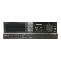
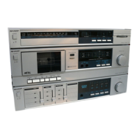
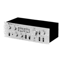
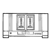
Lists and identifies all physical components and controls of the unit.

Disassembly Procedure

Disassembly Precautions

Provides critical safety and handling instructions before disassembling the unit.

Exploded View

IC Terminal Lists

Analog Switch IC Terminals (LC7823)

Lists pin names and functions for the LC7823 analog switch IC.

Graphic Equalizer Switching IC Terminals (LC7520)

Lists pin names and functions for the LC7520 graphic equalizer switching IC.

Circuitry Description

Schematic Diagram Notes

P.W. Board Wiring

Schematic Diagrams

Equivalent Circuits and Component Types

Equivalent Circuits of ICs

Displays block diagrams and pin configurations for key integrated circuits used in the unit.

Types of Transistors and LEDs

Identifies common transistor and LED types used, with their pin configurations.

Supply Leads and Packing

Replacement Parts List

Service Information

Supply Voltage Setting

Instructions for changing the unit's operating voltage from 220V to 110V.