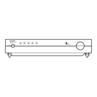
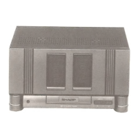
SM-SX100
– 1 –
SM-SX100
• In the interests of user-safety the set should be restored to its
original condition and only parts identical to those specified be
used.
SERVICE MANUAL
SHARP CORPORATION
No. S3021SMSX100/
This document has been published to be used
for after sales service only.
The contents are subject to change without notice.
CONTENTS
Page
IMPORTANT SERVICE NOTES (FOR U.S.A. ONLY)........................................................................................................2
IMPORTANT SERVICE NOTES (FOR U.K. ONLY) ...........................................................................................................2
SPECIFICATIONS ............................................................................................................................................................. 3
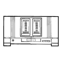
NAMES OF PARTS ........................................................................................................................................................... 3
OPERATION MANUAL ...................................................................................................................................................... 6
DISASSEMBLY.................................................................................................................................................................. 7
ADJUSTMENT ................................................................................................................................................................. 10
INTRODUCTION OF CIRCUIT OUTLINE ....................................................................................................................... 12
EXPLANATION OF 1-BIT UNIT ....................................................................................................................................... 18
WIRING PROCESS DIAGRAM ....................................................................................................................................... 21
BLOCK DIAGRAM ........................................................................................................................................................... 24
NOTES ON SCHEMATIC DIAGRAM .............................................................................................................................. 26
TYPE OF TRANSISTOR AND DIODE............................................................................................................................. 26
SCHEMATIC DIAGRAM/WIRING SIDE OF P.W.BOARD ............................................................................................... 27
WAVEFORMS OF CD CIRCUIT ...................................................................................................................................... 50
TROUBLESHOOTING ..................................................................................................................................................... 51
FUNCTION TABLE OF IC................................................................................................................................................ 55
PARTS GUIDE/EXPLODED VIEW/PACKING METHOD (FOR U. K. ONLY)/PACKING OF THE SET (FOR U.S.A. ONLY)