1
SMD2470AHAUPDATE
S17M398SMD0AH
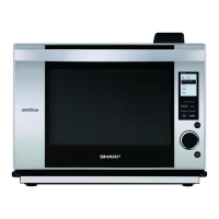
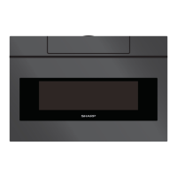
MICROWAVE
DRAWER MODEL
SERVICE MANUAL
TABLE OF CONTENTS
Page
PRECAUTIONS TO BE OBSERVED BEFORE AND DURING SERVICING TO
AVOID POSSIBLE EXPOSURE TO EXCESSIVE MICROWAVE ENERGY ..................... INSIDE FRONT COVER
BEFORE SERVICING ....................................................................................................... INSIDE FRONT COVER
WARNING TO SERVICE PERSONNEL ................................................................................................................. 3
MICROWAVE MEASUREMENT PROCEDURE ..................................................................................................... 4
FOREWORD AND WARNING ............................................................................................................................... 5
PRODUCT SPECIFICATIONS ............................................................................................................................... 6
SCHEMATICS ...................................................................................................................................................... 10
TROUBLE SHOOTING GUIDE.............................................................................................................................11
TEST PROCEDURES .......................................................................................................................................... 13
MICROWAVE DRAWER DISASSEMBLY ............................................................................................................. 25
WIRING DIAGRAMS ............................................................................................................................................ 32
PARTS LIST ......................................................................................................................................................... 33
PACKING AND ACCESSORIES .......................................................................................................................... 39
This document has been published to be used for after sales service only. The contents are subject to change without notice.
SHARP ELECTRONICS CORPORATION
SMD2470AHA
In the interest of user-safety the unit should be restored to its original condition and only parts identical to those specified should
be used.
WARNING TO SERVICE PERSONNEL:
This service manual is intended for use by persons having electrical and mechanical training and a level
of knowledge of these subjects generally considered acceptable in the appliance repair trade. SHARP
ELECTRONICS CORPORATION cannot be responsible, nor assume any liability, for injury or damage of any
kind arising from the use of this manual.
* FOR SERIAL NUMBERS: 500001 ~ AND ABOVE
Units with Serial Number range 500001 ~ and above employ a change to the
connectors on various Components, Harnesses and PWB’s.
Use this Service Manual for all units with the Serial Number range
500001 ~ and above.
*NOTE: