6
SX68JF100
6-1 6-2
SERVICE ADJUSTMENT
PIF CHECK ADJUSTMENT
NO. Adjustment part Adjusting procedure and conditions Waveform and others
1 RF-AGC
Cut-in adjustment
(Already preset.)
1 E-12CH (PAL colour Bar) is received.
Electric field intensity: 54 ±1dBµV (75 Open)
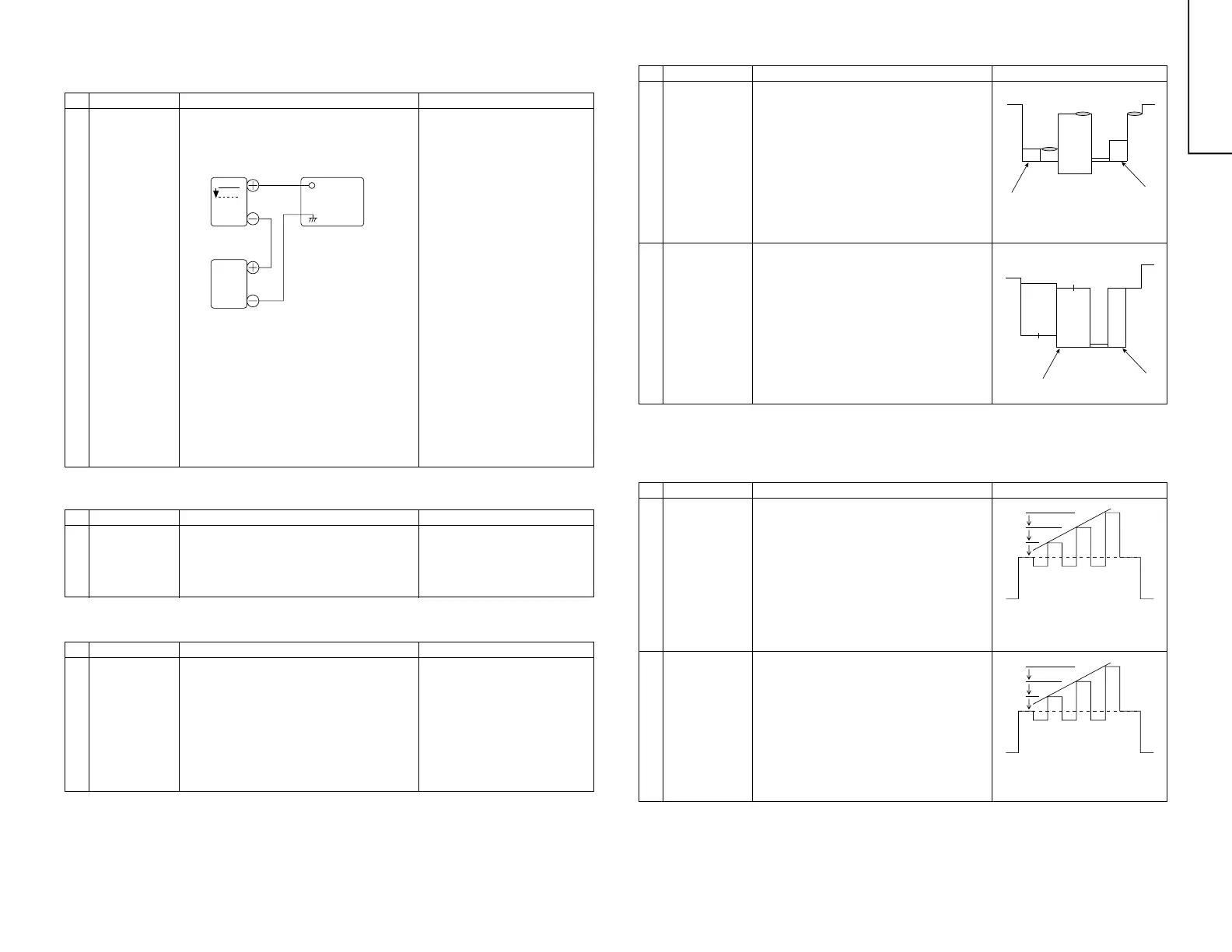
2 Connect the oscilloscope to TP210 as shown
below.
Note:If the impedance converter of
50/75 is not used at the elec-
tric field intensity meter of
50Ω system, set 52 ± 1dBV
for 54 ± 1dBµV (75Ω Open).
Moreover, take care for the
loss if the converter is used.
* If there is not any problem when
the several lots of the model
which employs the relevant tuner
is checked, apply the check of
only 5 and 6.
3 Drop the input electric field intensity to 51 ±
1dBµV (75Ω Open).
4 Under the conditions 1 and 3, TP210 voltage
does not vary.
Raise the input signal electric field strength to
60 ± 1dBµV (75Ω Open), and verify that it is
0.1V or more lower than TP210 of 1 and 3.
5 Set the signal at 63 to 67dBµV, and make sure
there is no noise.
6 Set the signal at 90 to 95dBµV, and make sure
that there is no cross modulation beat.
0.1V
Bias
box
TP210
TV SETOscilloscope
Bias Box: About 4.5V
NO. Adjustment part Adjusting procedure and conditions Waveform and others
VIDEO LEVEL ADJUSTMENT
NO. Adjustment part Adjusting procedure and conditions Waveform and others
SERVICE ADJUSTMENT
1 VIDEO DET
Level adjustment
R220
(in the main unit)
1 E-12CH B/G-PAL colour bar (100% white bar)
is received.
2 Adjust R220 to make the video output of the
AV-OUT terminal become 1.0 ± 0.05Vp-p at
the 75Ω terminator.
1 Digital comb filter Y
level adjustment
R5467
(in the DID unit)
1 Input PAL colour bar signal (100% white col-
our bar) of 1.0Vp-p at the 75Ω terminator from
AV-IN terminal.
(Input level 1.0 ± 0.05Vp-p)
2 Connect the oscilloscope to YA (pin (7) of
TP5462.)
3 Adjust R5467 to make the Y signal (100%
white) of TP5462 become 2.0 ± 0.1Vp-p.
* Verify that all are linearly amplified. (100% white
area must not be collapsed.)
<Reference>
When it is adjusted at E-12ch, take
care for the voltage value.
Adjustment value (TP5462) 2.0Vp-p
NO. Adjustment part Adjusting procedure and conditions Waveform and others
PAL CHROMA ADJUSTMENT
1-1 SUB-COLOUR
(SUB COL)
I
2
C bus
adjustment
(RF signal)
1 E-12CH(PAL colour bar) is received.
2 Make the picture normal with the remote con-
troller.
3 Connect the oscilloscope to TP3802. (10:1
probe is used.)
Range: 2V/Div.
Sweep time : 20µsec/Div.
4 Set the "SUB COL" adjustment mode with the
remote controller, and vary the sub colour data
to make 75%W of the PAL colour bar and RED
at the same level for adjustment shown in
Fig. 1.
NO. Adjustment part Adjusting procedure and conditions Waveform and others
NTSC CHROMA ADJUSATMENT
1-1 SUB-TINT
(SUB TINT)
I
2
C bus
adjustment
(RF signal)
1 Select the "SUB-TINT" adjustment mode (au-
tomatic Y cut) to receive JA-8CH(NTSC col-
our bar).
2 Connect the oscilloscope to TP3803 (B-out).
Range : 50mV/Div. (AC)
Sweep time: 10µsec/Div. (10:1 probe is used.)
3 Vary the sub tint data to adjust the waveform
to be gained as shown in Fig. 3.
TP3803………(KY) 6 pin
1-2 SUB-COLOUR
(SUB COL
DVD)
I
2
C bus
adjustment
(DVD signal)
1 DVD signal is received. (Half colour bar signal)
2 Make the picture normal with the remote con-
troller.
3 Connect the oscilloscope to TP3802. (10:1
probe is used.)
Range : 2VA/Div.
Sweep time: 20µsec/Div.
4 Set the "SUB COL DVD" adjustment mode with
the remote controller, and vary the sub colour
data to make 100%W of the colour bar and
RED at the same level for adjustment shown
in Fig. 2.
1-2 SUB-TINT
(SUB TINT DVD)
I
2
C bus
adjustment
(DVD signal)
1 Select the "SUB-TINT DVD" adjustment mode
(automatic Y cut) to receive the DVD colour
bar signal.
2 Connect the oscilloscope to TP3803.
Range : 50mV/Div. (AC)
Sweep time: 10µsec/Div. (10:1 probe is used.).
3 Vary the sub tint data to adjust the waveform
to be gained as shown in Fig. 4.
4 Release the adjustment mode.
Cy G
W Y 100%W Mg
Mg
R
B
Fig. 1
Fig. 2
Fig. 4
A=B=C
Fig. 3
A=B=C
A
B
C
W Y Cy G Mg R B BLK
A
B
C
W Y Cy G Mg R B BLK
Cy G
75%W Y 100%W Mg R
B