13
SX68JF100
13-1 13-2
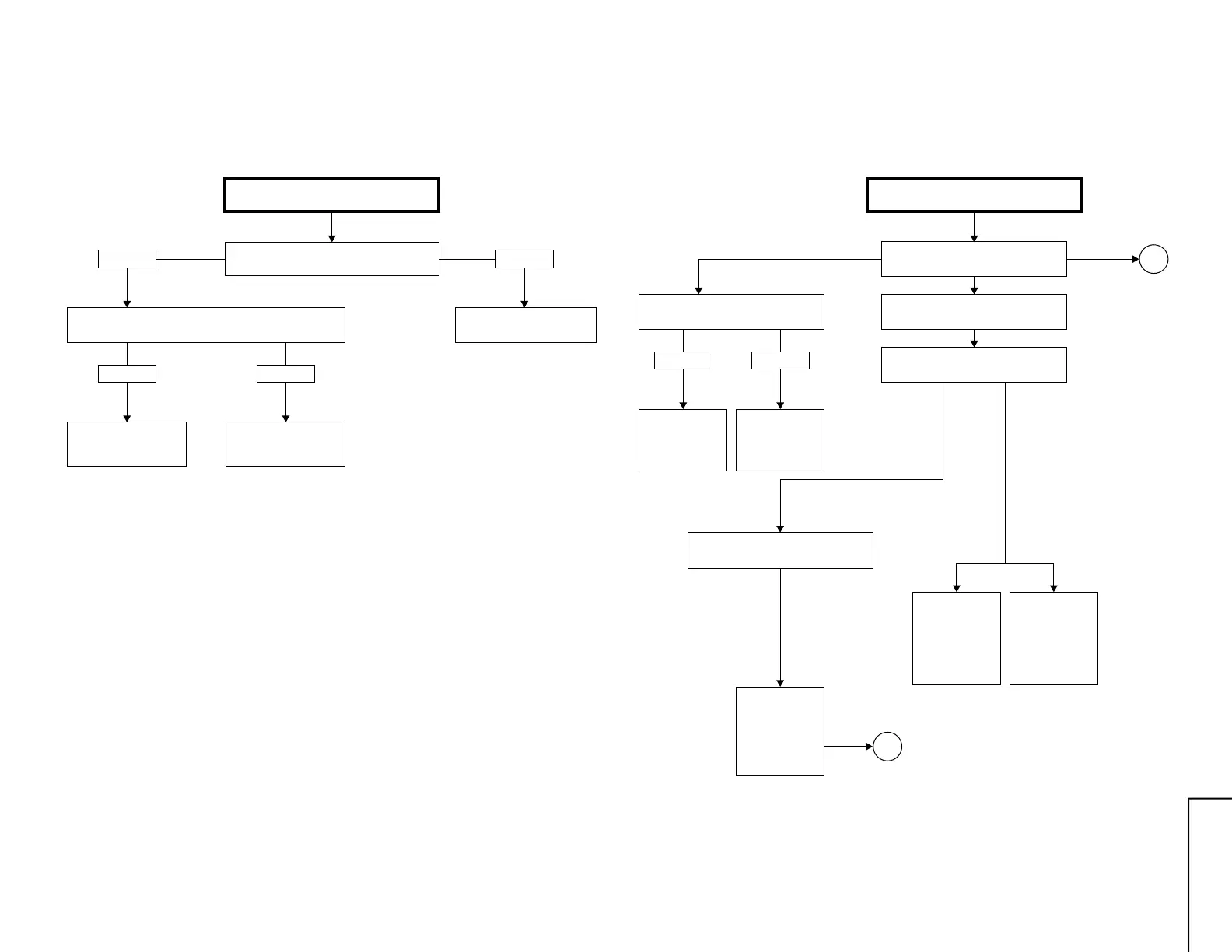
TROUBLE SHOOTING TABLE
Check the voltage at pin (6) of IC1501 and
pin (6) of IC1500.
NO VERTICAL SCAN
Circuits to be checked:
» IC1500, 1501 and its
peripheral circuit
Check IC1500, IC1501
and related circuits
Normal Abnormal
Normal
Check IC2801 and its
peripheral parts.
Check vertical trigger pulse at pin (31) of IC2801.
Check L1500, D1576 and
R1576.
Abnormal
Note 1: Make sure that not for the horizontal centering mode.
Turn on the service mode. (Short J351 and J352.)
Then when you press "- / --" key on the remote you
can get in the horizontal centering mode.
Note 2: The vertical sync signal must be fed to pin (2) of
IC1000 in oder not to activate the vertical no-scan
protector.
Take this measure with the protector circuit for the
troubleshooting on the following pages.
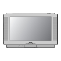
TROUBLE SHOOTING TABLE (Continued)
Does D1202 (POWER LED) turn on?
D1202 (POWER LED) turns on and
off.
NO RASTER
Circuits to be checked:
» Power circuit.
» Video circuit.
» Protector cirucit.
» Peripheral circuit of
Bus Line.
Normal
Check connector (KY) and (H) of CRT.
Does RY2700 turn on?
Turns on, but soon turns off.
Abnormal
Check IC3801,
IC3802 and
IC3803.
Check protector
circuit and its
related parts (2)
of IC1000
V-PULSE.
Check the
power circuit
consisting of
IC1701, IC1702,
D1700 and etc.
Yes
Yes (RED)
Yes
(Bus error)
No
See many often
D1202 flashes
in red.
This indicates
which IC to
check up.
No
A
B
Check IC2801.