7
SX68JF100
7-1 7-2
adjust
Fig. 5( a)
Fig. 5 (b)
Fig. 6 (a)
OFF SET
Fig. 7 (a)
Fig. 6 (b)
Fig. 7 (b)
OFF SET
NO. Adjustment part Adjusting procedure and conditions Waveform and others
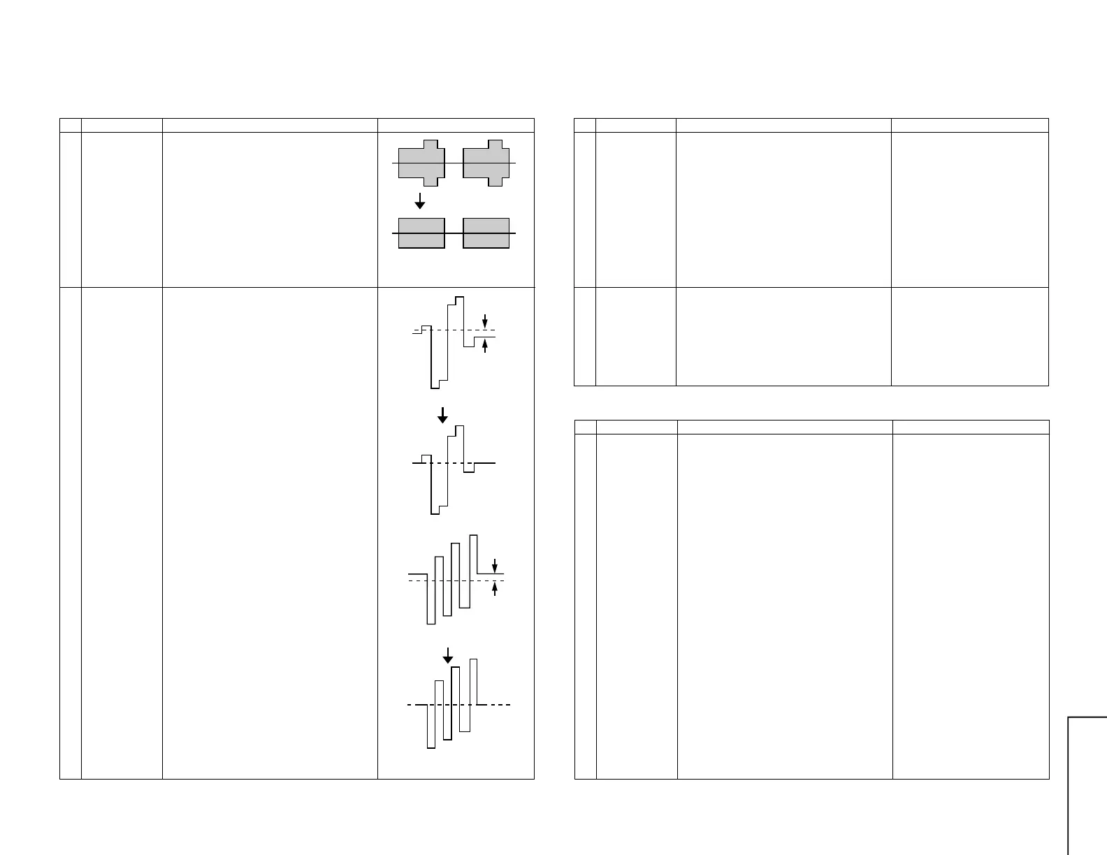
SECAM CHROMA ADJUSTMENT
1 BELL FILTER f0
(SCM BELL)
I
2
C bus
adjustment
1 Receive Oi-5CH(SECAM colour bar).
2 Select the "SCM BELL" fo adjustment mode.
3 Connect the oscilloscope to TP901 of main.
(TP2901 in VCJ unit)
Range : 10mV/Div. (AC)
Sweep time: 20µsec/Div. (10:1 probe is used.)
4 Vary the bell filter data to align the waveform
to be the nearest to that in Fig. 5 (b).
(Arrange the level to gain the whole balance.)
2 SECAM black
level R-Y/B-Y
(R-Y and B-Y)
I
2
C bus
adjustment
1 Receive Oi-5CH(SECAM colour bar).
2 Select SECAM black level adjustment "R-Y"
mode.
3 Connect the oscilloscope to TP802 (TP2804
in VCJ unit) of the main.
Range: 10mV/Div.
Sweep time: 20µsec/Div. (10:1 probe is used.)
4 Vary R-Y data to minimize the offset between
the non-signal line and signal line as shown in
Fig. 6 (b).
5 Select SECAM black label adjustment "B-Y"
mode.
6 Reconnect the oscilloscope to TP803 (TP2805
in VCJ unit) of the main.
The conditions are the same as in Item (3).
7 Vary B-Y data to minimize the offset between
the non-signal line and signal line as shown in
Fig. 7 (b).
* To be at the same levbel.
NO. Adjustment part Adjusting procedure and conditions Waveform and others
1 SUB SOUND
(SUB VOL)
(I
2
C bus
adjustment)
1 Receive E-12ch (PAL colour bar). Signal con-
tent: 400Hz 100% Mod.
2 Connect the probe of the meter to (SI) con-
nector. (See Note)
3 Select "SUB VOL" in the service mode.
4 Adjust the sub-sound data to make the meter
indicate 8.5Vrms (at L-ch).
Adjustment value : 8.5 ± 0.4Vrms
NO. Adjustment part Adjusting procedure and conditions Waveform and others
SIF (NICAM/IGR) ADJUSTMENT
1 VCO COIL
T2300
(in the NICAM
unit)
1 Receive E-69CH (PAL colour bar).
(Set the receiving frequency at AFT OFF Ex.
E-69=855.25 MHz.)
2 Connect the digital voltmeter to TP301 (in the
main unit).
3 Verify that it is turned counterclockwise to 0V
and clockwise to 5V, and adjust T2300 to make
the DC voltage of TP2300 become 2.5 ± 0.1V
in the range.
<Single-unit adjustment> - For your Reference.
Vcc 5 ± 0.1V
IF input frequency 38.9MHz ± 10kHz
Control it under these conditions.
Adjust T2300 to make the DC voltage of TP2300
(in the NICAM unit) become 2.5 ± 0.1V.
After single-unit adjustment, check the practical
setup.
Align the receiving frequency to the select chan-
nel frequency. (AFT OFF)
The checked TP301 in the main unit voltage must
be 2.5 ± 1.0V.
(Take care that ±1.0 is considered for the Vcc dif-
ference between the single unit and unit, Fo dif-
ference and so on, but is not the adjustment pre-
cision.)
2 Noise mute
check
1 Receive E-12CH (PAL colour bar).
2 Maximize the sound volume to verify that the
sound is output from the speaker. Then, set
the non-signal state.
3 At this time, verify that the audio mute oper-
ates.
4 After checking the operation, set the sound
volume to be the minimum.
Note:
* SPATIALIZER ..... OFF
* S-Normal state
* S-VOL ................ Max
* S-BOOSTER ...... OFF
SOUND LEVEL ADJUSTMENT