27
VL-PD3AS/AH/AE
No. Description
E007 CAP FG is not input for more than 1 second.
E011 Though L/M rotates in the forward direction
for more than 5 seconds (or 10 seconds),
the set does not enter the next mode.
E012 Though L/M rotates in the reverse direction
for more than 5 seconds (or 10 seconds),
the set does not enter the next mode.
No. Description
E020 DRUM FG is not input for more than 100 m/sec.
E025 The TU reel sensor is activated.
E026 The SU reel sensor is activated.
Note: E020, 025 or 026 occurs often due to scratches on the tape, condensation, etc. rather than due to trouble of the set. Therefore,
if E020, 025 or 026 occurs, be sure to take out the cassette, and then play it back again to check whether the set operates
properly.
• Mechanism Error Message
When an error occurs (while "EJECT THE CASSETTE", is displayed.), hold down the "STOP" key for about 3 seconds to see what
kind of error occurs.
1. PLL VCO adjustment
Mode VCR ADJ mode
Procedure 1) Playback the alignment tape (or a self-recorded tape).
2) Call the adjustment mode (V-ADJ).
3) Set the address "2A" and call the data.
4) Set the called data with the FF/REW key to the point where the playback screen appears.
(At this time, the screen full of block noise is OK.)
Examples • During E
2
PROM replacement. • During circuit board (Main) replacement.
ADJUSTING THE ELECTROMAGNETIC CONVERSION CIRCUIT SYSTEM
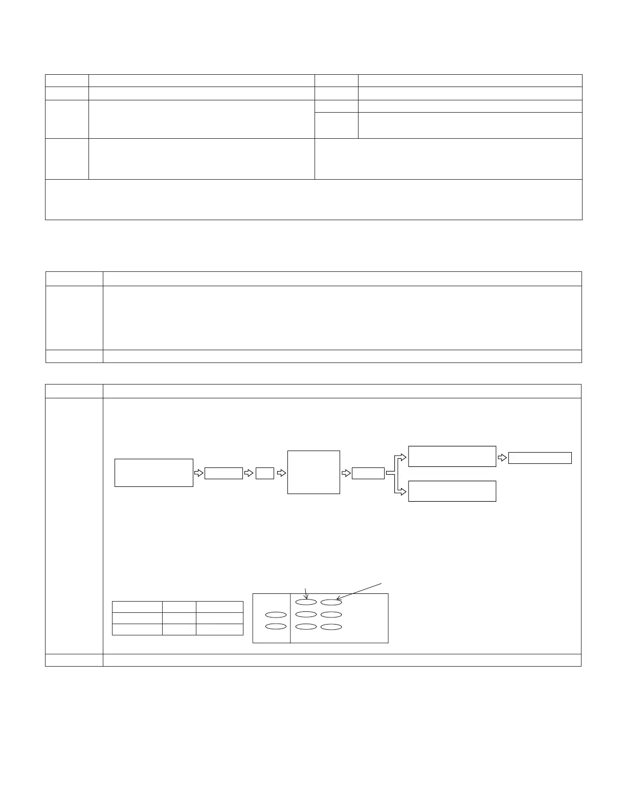
2. Phase and equalizer adjustment → (Performed in the VCR mode)
Mode VCR ADJ mode
Procedure 1) Load a self-recorded tape into the deck.
2) After playback for 3 minutes, select the test mode 0F using the remote control for adjustment to start the
automatic adjustment. (The following sequence is automatically performed.)
3) Error rate check
Select and fix the TEST MODE 0B on the adjustment remote control.
4) Manual adjustment method (video adjustment mode)
* Perform this adjustment with the self-recording/playback in the LP mode.
For phase, vary the data for the address 26 and 2B, and for equalizer, vary the data for the address 25 and 27,
to set the error rate is made as small as possible.
Examples • During mechanism replacement. • During circuit board (Main) replacement. • During E
2
PROM replacement.
Tape is EJECT.
The built-in VI/O
colour bar is recorded.
VS REW
PB
Phase and
equalizer are
adjusted
automatically.
Judgment
OK:
Blue LCD comes on.
NG:
Red LCD comes on.
Synchronization error
Error rate
H
L
Phase Equalizer
H ch side 2B 27
L ch side 26 25
Synchronization error 20 or less
Error rate 200 or less (SP Mode)
330 or less (LP Mode)