28
VL-PD3AS/AH/AE
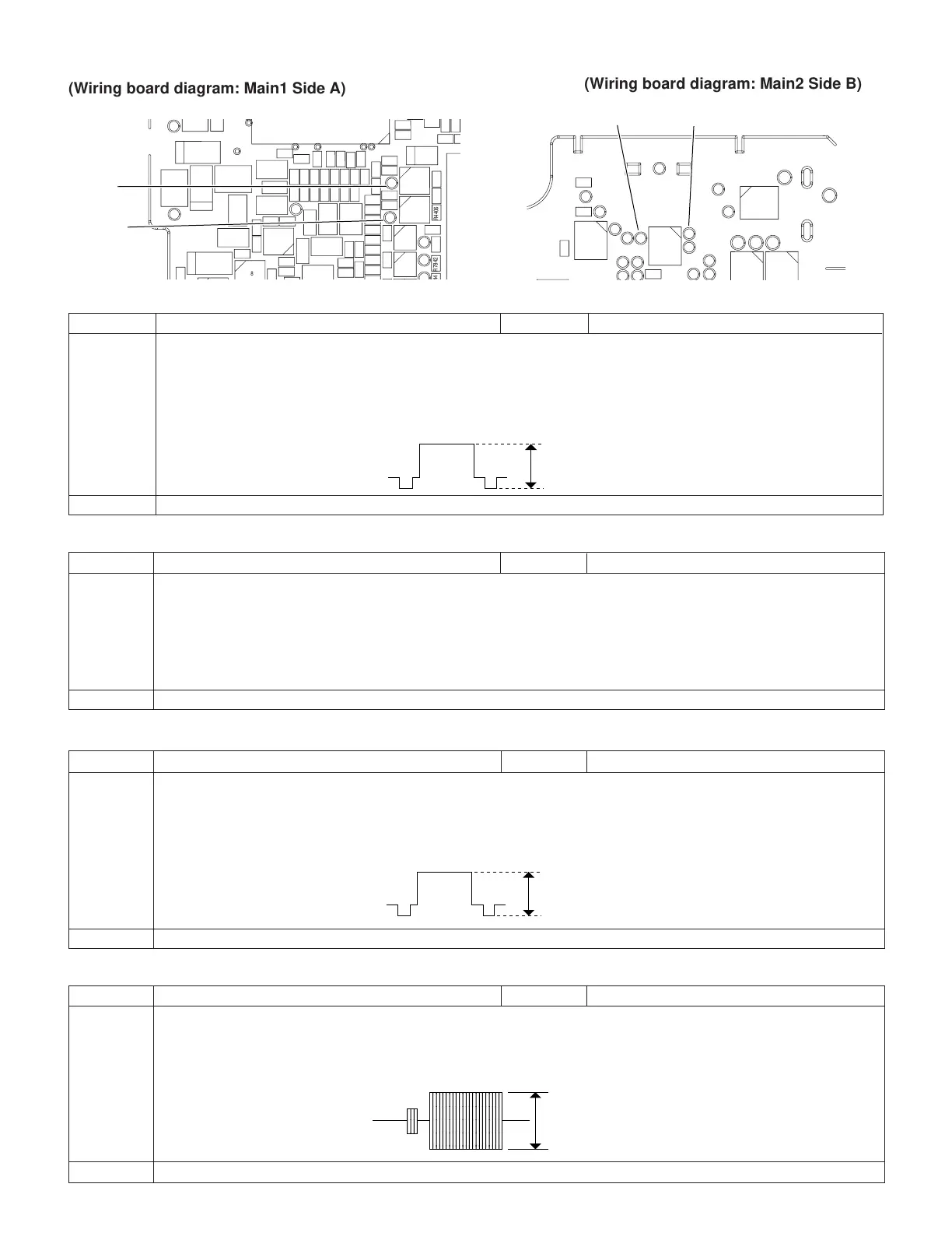
1. PCO D/A-Y adjustment
Test point TL4401 (connected to oscilloscope) Mode EE mode
Procedure 1) Connect the AVS cable and then connect it to the monitor (TO).
2) Call the adjustment mode (V-ADJ).
3) Set the address to "22", and call the date.
(100% white signal is output.)
4) Vary the date with the FF and REW keys to set the signal appearing at TL4401 to 0.5Vp-p ± 0.025Vp-p.
Examples • During E
2
PROM replacement. • During IC4401 replacement.
ADJUSTING THE VIDEO I/O CIRCUIT SYSTEM
2. PCO D/A-C adjustment
Test point TL4402 Mode EE mode
Procedure 1) Connect the AVS cable and then connect it to the monitor (TO).
2) Call the adjustment mode (V-ADJ).
3) Set the addresses C0/C1/C2/C3 to 90/E6/80/80, respectively.
4) Set the address to "23", and call the data.
5) Vary the data with the FF and REW keys to set the signal appearing at TL4402 to 0.52Vp-p ± 0.05Vp-p.
6) Reset the addresses C0/C1/C2/ C3 to FF.
Examples • During E
2
PROM replacement. • During IC4401 replacement.
3. DAC Y adjustment
Test point TL5206 (connected to oscilloscope) Mode EE mode
Procedure 1) Connect the AVS cable and then connect it to the monitor (TO).
2) Call the adjustment mode (V-ADJ).
3) Set the address to "2D", and call the data.
(100% white signal is output.)
4) Vary the data with the FF and REW keys to set the signal appearing at TL5206 to 1.0Vp-p ± 0.05Vp-p.
Examples • During E
2
PROM replacement. • During IC4401 replacement. • During IC1401 replacement.
1.0±0.05
4. DAC C adjustment
Test point TL5208 Mode EE mode
Procedure 1) Connect the AVS cable and then connect it to the monitor (TO).
2) Call the adjustment mode (V-ADJ).
3) Set the address to "24", and call the data.
4) Vary the data with the FF and REW keys to set the signal appearing at TL5208 to 0.64 ± 0.05Vp-p.
Examples • During E
2
PROM replacement. • During IC4401 replacement. • During IC1401 replacement.
0.5±0.025
0.64±0.05
,,,,
,,,,
,,,,
,,,,
yyyy
yyyy
yyyy
yyyy
(Wiring board diagram: Main2 Side B)
(Wiring board diagram: Main1 Side A)
R4406
4 R7842 C7842
R7840
TL7821
TL7820
Q7861 Q7862
R7862 R7863
TL4402
C7841
R7843
C7840
R7841
C4406
R4407
C7821 R7823
L4401
R7822
R7821
C7820
C4404
C4402
C4403
R4402
R4403
C4473
C4472
R4475
486
Q4471
R4474
R4473 R4476
Q4481
C4482
L4481
C4483
488
TL5032
TL5031
L203
FB201
C207
C204
FB
L201
TL214
L4402
TL206
C4410
C4401
R4401
C209
TL5030
TL201
R7871 R7878
C210
R7870 R7873
TL4441
R7872 R7877
C211
R7875 R7876
C213
R7874 R4424
C208
R4423 R4425
C212
R4420 R4422
TL202
C214
R4421
TL203
C4405
R4405
C4449 R4435
R4438
R4439
R4436
R4437
TL4401
C217
C216
Q4433
Q4434
C4448
R4457
C4412 R4404
R4408
C446
C4
R446
TL4401
PCO D/A-Y
TL4402
PCO D/A-C
R5211
R5206
R5210
TL5201
FL5201
TL5202
TL5203
TL3337
TL3335
TL5204
TL3336
TL3334
TL5206
R5212
TL5205
FL5202
TL5207
TL5208
TL3308TL3324
TL3325
TL5209
TL5210
TL7405
L7402
TL7404
FL5203
TL7403
TL7401
L7401
TL7402
TL5206
DAC Y
TL5208
DAC C