XL-S10
7 – 1
AudioXL-S10Service ManualXLS10MarketE
CHAPTER 7. OTHERS
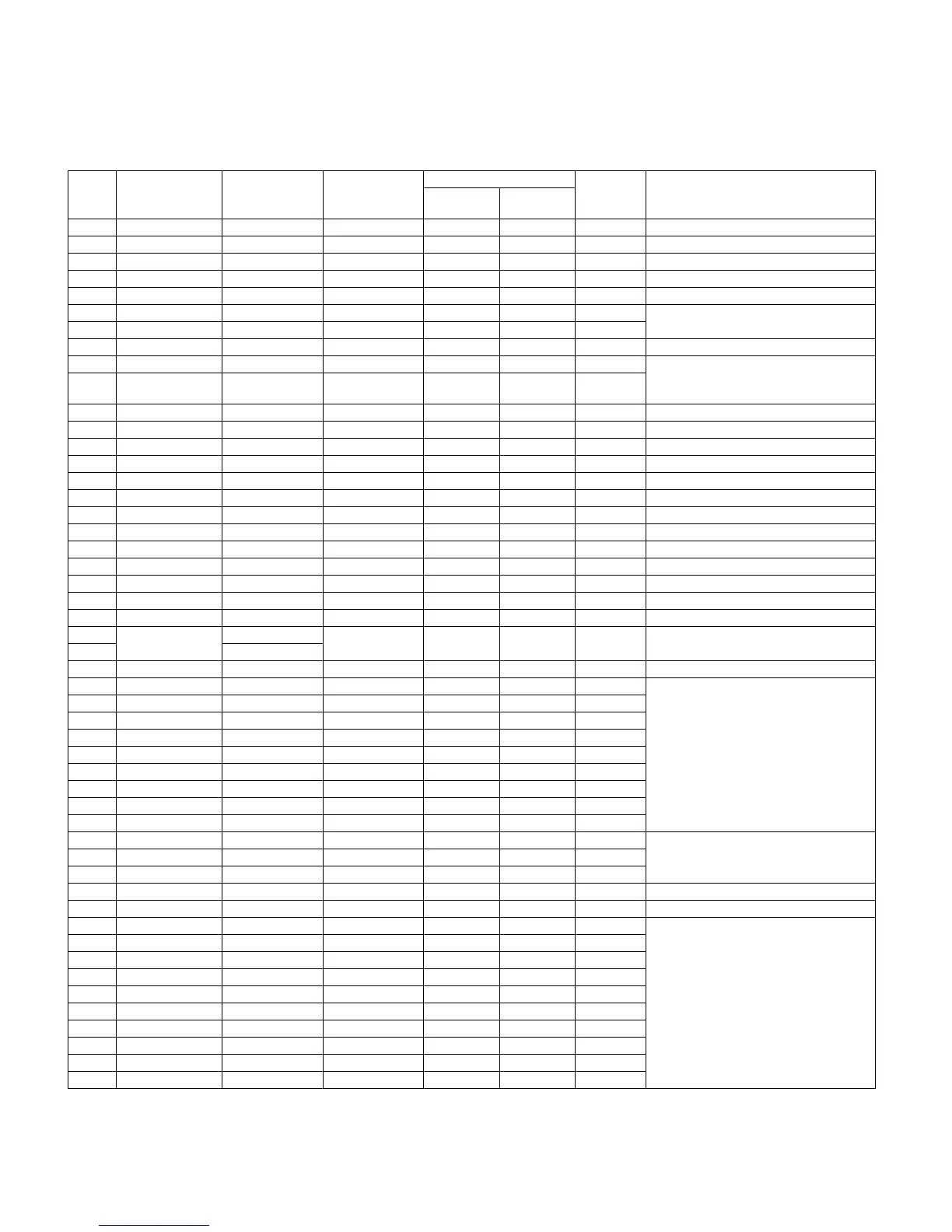
[1] FUNCTION TABLE OF IC
IC701 RH-iXA007SJZZ: System Microcomputer (IXA007SJ) (1/2)
IC701 RH-iXA019SJZZ: System Microcomputer (IXA019SJ) (1/2)
In this unit, the terminal with asterisk mark (*) is (open) terminal which is not connected to the outside.
Pin
No.
Port Name Terminal Name Input/Output
Terminal status Option
resistor,
etc.
Function
Reset Active
1 I_TU_DATA P14 Input L H/L LV23002 serial data input
2 O_TU_CLK P15 Output L H/L LV23002 serial clock output
3 O_FUNC_DATA P16 Output L H/L BD3881 CONT output
4 O_FUNC_CLK P17 Output L H/L BD3881 CONT output
5 — RES Input RESET
6 — XT1/AN10 — Terminal connecting resonator for sub
clock f=32.768kHz
7 — XT2/AN11 —
8 GND VSS1 — GND
9 — CF1 — Terminal connecting resonator for main
clock f=8.5MHz
10 — CF2 —
11 VDD1 VDD1 — Power supply +5.0V
12 I_HOLD P80/AN0 Input H H Power supply voltage monitoring input
13 I_VP_CHK P81/AN1 Input A/D Input Abnormal voltage monitoring input
14 I_CD_LID P82/AN2 Input L H/L CD lid OPEN detection SW input
15 I_CD_DRF P83/AN3 Input L H/L CD DRF signal input
16 I_TP_STATE P84/AN4 Input A/D Input DECK status monitoring input
17 I_VOL_ENC P85/AN5 Input A/D Input VOL encoder input
18 I_KEY1 P86/AN6 Input A/D Input Main unit KEY input 1
19 I_KEY2 P87/AN7 Input A/D Input Main unit KEY input 2
20 I-SUFIX P70/INT0/AN8 Input A/D Input Destination select input
21 I_CD_WRQ P71/INT1/AN9 Input L H/L CD WRQ signal input
22 O_POWER P72/INT2 Output L H/L Power ON/OFF output
23 I_REM P73/INT3 Input L H/L Remote control pulse signal input
24 IO_EEP_DATA S0/PA0 Input/Output L H/L EEPROM control data input/output
(Pull-down at 100k? when not used)
25 S1/PA1
26 O_EEP_CLK S2/PA2 Output L H/L EEPROM control clock output
27* NC S3/PA3 Output L L “L” fixed output
28* NC S4/PA4 Output L L
29* NC S5/PA5 Output L L
30* NC S6/PA6 Output L L
31* NC S7/PA7 Output L L
32* NC S8/PB0 Output L L
33* NC S9/PB1 Output L L
34* NC S10/PB2 Output L L
35* NC S11/PB3 Output L L
36 S19 S12/PB4 — LCD segment output
37 S18 S13/PB5 —
38 S17 S14/PB6 —
39 VDD2 VDD2 — Microprocessor power supply +5.0V
40 GND VSS2 — Microprocessor power supply GND
41 S16 S15/PB7 — LCD segment output
42 S15 S24/PD0 —
43 S14 S25/PD1 —
44 S13 S26/PD2 —
45 S12 S27/PD3 —
46 S11 S28/PD4 —
47 S10 S29/PD5 —
48 S09 S30/PD6 —
49 S08 S31/PD7 —
50 S07 S32/PE0 —