EasyManua.ls Logo

Sharp VZ-1600H(S) User Manual

Sharp VZ-1600H(S)
48 pages
To Next Page IconTo Next Page
Page #1 background imageLoading...
Page #1 background image
VZ-1600H(S)
SHARP
SERVICE
MANUAL
/SERVICE-ANLEITUNG/
MANUEL
DE
SERVICE
PHOTO:
VZ-1600H(S)
DO
[sacavsvsrem)°
@Noise
reduction
system
manufactured
under
license
from
Dolby
“Dolby”
and
the
double-D
symbol
are
trademarks
of
Dolby
Laboratories
Licensing
Corporation.
e
Gerauschunterdruckungssystem
unter
Lizenz
von
Dolby
Laboratories
Licensing
Corporation
hergestellt.
Das
Wort
‘‘Dolby’’
und
das
Sym-
bol
des
doppelten
D
sind
die
Warenzeichen
von
Dolby
Laboratories
Laboratories
Licensing
Corporation.
Licensing
Corporation.
e
Réducteur
de
bruits
Dolby:
Circuit
fabriqué
sous
licence
des
Dolby
Le
mot
“Dolby”
et
le
symbole
double
D
sont
des
marques
déposées
des
Dolby
Laboratories
Licens-
Laboratories
Licensing
Corporation.
ing
Corporation.
$3555VZ1600HS
VZ-1600H(S)(W)
VZ-1600H(BK)(BR)
VZ-1600E(BK)
Note
for
users
in
UK
Recording
and
playback
of
any
material
may
require
consent
which
SHARP
are
unable
to
give.
Please
refer
particularly
to
the
provi-
sions
of
Copyright
Act
1956,
the
Dramatic
and
Musical
Performers
Protection
Act
1958,
the
Performers
Protection
Acts
1963
and
1972
and
to
any
subsequent
statutory
enactments
and
order.
orignal
condition
used.
@!m
Interesse
der
Benutzer-Sicherheit
sollte
dieses
Gerat
wieder
auf
seinen
ursprunglichen
Zustand
eingestellt
und
nur
die
vorge-
schriebenen
Teile
verwendet
werden.
©
Dans
|’intérét
de
la
sécurité
de
I‘utilisateur,
l'appareil
devra
étre
reconstitué
dans
@in
the
interests
of
user-safety
the
set
should
be
restored
to
its
and
only“parts
identical
to
those
specified
be
sa
condition
premiére
et
seules
des
piéces
identiques
a
celles
spécifiées,
doivent
étre
utilisées.
©INDEX
TO
CONTENTS
®INHALTSVERZEICHNIS
©TABLE
DES
MATIERES
Page
SPECIFICATIONS..............0.
2
STRINGING
OF
DIALCORD........
2
NAMES
OF
PARTS
............-..
5
DISASSEMBLY
...............
7,9
BLOCK
DIAGRAM
..............
11
STRINGING
OF
PLAYERWIRE
......
12
EFFECTIVE
KEY
OPERATION
REPLACEMENT
OF
PHONO
MOTOR
...
FUNCTIONS
OF
MICROCOMPUTER
|IC801
AND
ITS
PERIPHERAL
CIRCUIT
....15
MECHANICAL
ADJUSTMENT
....
18,
20
CIRCUIT
ADJUSTMENT........
22,
24
NOTES
ON
SCHEMATIC
DIAGRAM...
.
26
WIRING
OF
PRIMARILY
SUPPLY
LEADs
(For
UK)
EQUIVALENT
CIRCUIT
(BLOCK
DIAGRAM)
OF
IC
.....
27,
28
SCHEMATIC
DIAGRAM
..
.
31,
32,
35, 36, 37,
38,
43,
44
WIRING
SIDE
OF
P.W.BOARD
.
29,
30, 33,
34,
39,
48,
42
PACKING
METHOD
(For
UK)........
45
EXPLODED
VIEW............
46-47
REPLACEMENT
PARTS
LIST.
....
50—59
SERVICE
INFORMATION.
.........
60
Seite
TECHNISCHECATEN
............
3
SPANNEN
DER
SKALENSCHNUR....
2,3
BEZEICHNUNG
DERTEILE
.......
5,6
ZERLEGEN
................
7-10
BLOCKSCHALTPLAN
............
11
SPANNEN
DES
PLATTENSPIELERDRAHTS
12,13
EFFEKTIVE
TASTENBEDIENUNG
AUSWECHSLUNG
DES
PLATTENSPIELERMOTORS
.......
13
FUNKTIONEN
DES
MIKROCOMPUTERS
1C801
UND
SEINER
PERIPHERIESCHALTUNG
........
16
MECHANISCHE
EINSTELLUNG
18-21
SCHALTUNGSEINSTELLUNG
....
22-25
ANMERKUNGEN
ZUM
SCHEMATISCHEN
SCHALTPLAN................
ERSATZSCHALTKREIS
(BLOCKSCHALTPLAN)
DES
INTEGRIERTEN
SCHALTKREISES
SCHEMATISCHER
SCHALTPLAN
31,
32,
35,
36,
37,
38,
43,
44
VERDRAHTUNGSSEITE
DER
LEITERPLATTE.
..
29,
30,
33,
34,
39-42
EXPLOSIONSDARSTELLUNG
....
46—49
ERSATZTEILLISTE
..........
50-59
Page
CARACTERISTIQUES
............
4
PASSAGE
DU
CORDON
DU
CADRAN
straw
oP
Sed
Gl
2,4
NOMENCLATURE
.............
5,6
DEMONTAGE
...............
7-10
DIAGRAMME
SYNOPTIQUE
........
11
PASSAGE
DU
FIL
DU
LECTEUR...
12,14
OPERATION
DE
TOUCHE
EFFICACE
13
REMPLACEMENT
DE
MONTEURS
DU
PHONO
3
ends
tee
phew
w
Led
three?
14
FONCTIONS
DU
MICRO-ORDINATEUR
1C801
ET DE
SES
CIRCUITS
PERIPHERIQUES
..............
17
REGLAGE
DE
MECANISME
.....
18-21
REGLAGE
DUCIRCUIT........
22—25
REMARQUES
CONCERNANT
LE
DIAGRAMME
SCHEMATIQUE
.......
26
CIRCUITS
EQUIVALENTS
(DIAGRAMME
SYNOPTIQUE)
DE
C!
27,
28
DIAGRAMME
SCHEMATIQUE
Pe
Oe
31,
32,
35,
36,
37,
38,
43,
44
COTE
CABLAGE
DE
LA
PLAQUETTE
DE
MONTAGE
IMPRIME
29,
30,
33,
34,
39-42
VUE
ENECLATE............
46—49
LISTE
DES
PIECES
DE
RECHANGE
.........---.-.
50-59
INFORMATION
DESERVICE
.......
60
SHARP
CORPORATION
Question and Answer IconNeed help?

Do you have a question about the Sharp VZ-1600H(S) and is the answer not in the manual?

Sharp VZ-1600H(S) Specifications

General IconGeneral
TypeStereo System
ModelVZ-1600H(S)
ManufacturerSharp
Record PlayerYes
TunerFM/AM
Cassette DeckYes
AmplifierYes
SpeakersYes

Summary

Specifications

General Specifications

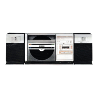
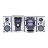
Details unit's power, dimensions, weight, and general features.

Amplifier Specifications

Details output power, input sensitivity, and impedance of the amplifier.

Cassette Deck Specifications

Details tape type, speed, wow/flutter, and frequency response.

Tuner Specifications

Details frequency range and sensitivity of the tuner.

Turntable Specifications

Details turntable type, speed, motor, tonearm, and cartridge.

Dial Cord Stringing Procedure

Dial Cord Routing Guide

Step-by-step instructions for stringing the dial cord.

Names of Parts

Part Identification and Labels

Identifies all physical parts of the unit with reference numbers.

Disassembly Guide

Disassembly Safety Precautions

Essential safety and handling guidelines before disassembling the unit.

Block Diagram

System Functional Block Diagram

Illustrates the overall functional relationships between major circuit blocks.

Effective Key Operation

Control Key Functionality Table

Details the effect of each control key in different operating modes.

Player Wire Stringing

Player Wire Routing Instructions

Guide for correctly routing and positioning the player wire.

Phono Motor Replacement

Phono Motor Replacement Procedure

Steps for replacing phono motors and necessary circuit modifications.

Microcomputer IC801 Functions

IC801 Pin Function Details

Explains the specific role and behavior of each pin on IC801.

Mechanical Adjustment (Tape Section)

Tape Section Adjustment Steps

Procedures for mechanical adjustments within the tape deck section.

Test Tapes for Measurement

Lists test tapes and their applications for performance checks.

Mechanical Adjustment (Player Section)

Player Section Adjustment Steps

Procedures for mechanical adjustments within the record player section.

FM Tuner Adjustment

FM IF/RF Alignment Procedures

Steps for aligning FM Intermediate Frequency and Radio Frequency circuits.

VCO Frequency Alignment

Procedure for adjusting the Voltage Controlled Oscillator frequency.

AM/LW Tuner Adjustment

AM/LW IF Alignment Procedures

Steps for aligning AM/LW Intermediate Frequency circuits.

AM/LW RF Alignment Procedures

Steps for aligning AM/LW Radio Frequency circuits.

Schematic Diagram Notes

Interpretation of Schematic Symbols and Voltages

Explains symbols, voltage measurements, and conditions for schematic interpretation.

Primary Supply Lead Wiring (UK)

Primary Supply Lead Wiring Diagrams

Shows wiring for primary supply leads and IC equivalent circuits.

Printed Wiring Board Layout

P.W. Board Wiring Side Diagram

Illustrates the wiring layout on the component side of P.W. Boards.

Schematic Diagram

Overall System Schematic Diagram

Provides the complete schematic for the entire audio system.

Printed Wiring Board Layout

P.W. Board Wiring Side Diagram

Illustrates the wiring layout on the component side of P.W. Boards.

Schematic Diagram

Mechanism/Audio PWB Schematic

Detailed schematic for the mechanism and audio circuit board.

Printed Wiring Board Layout

P.W. Board Wiring Side Diagram

Illustrates the wiring layout on the component side of P.W. Boards.

Printed Wiring Board Layout

P.W. Board Wiring Side Diagram

Illustrates the wiring layout on the component side of P.W. Boards.

Schematic Diagram

Mechanism/Audio PWB Schematic

Detailed schematic for the mechanism and audio circuit board.

Packing Method (UK Only)

Switch, Button, and Knob Settings for Packing

Recommended settings for controls during packing for shipment.

Mechanism Exploded View

Mechanism Exploded Parts Diagram

Visual breakdown of the mechanism showing individual parts.

Cabinet Exploded View

Cabinet Exploded Parts Diagram

Visual breakdown of the cabinet showing individual parts.

Replacement Parts List

Integrated Circuits, Transistors, and Diodes

List of replacement ICs, transistors, and diodes with part numbers.

Other Electronic Components List

List of other replacement electronic components with part numbers.

Replacement Parts List

Capacitor Specifications

List of replacement capacitors including values and voltage ratings.

Resistor Specifications

List of replacement resistors including values and wattage.

Replacement Parts List

Resistor Specifications (Continued)

Further listing of replacement resistors with values and wattage.

Replacement Parts List

Resistor Specifications (Continued)

Continued listing of replacement resistors with values and wattage.

Replacement Parts List

Resistors and Switches List

List of replacement resistors and switches with specifications.

Mechanical Parts List

Mechanical Part Identification

Identifies mechanical parts with reference numbers and names.

Replacement Parts List

Circuit Parts and Connectors List

List of replacement circuit parts and connectors with part numbers.

Service Information

Supply Voltage Setting Procedure

Instructions for configuring the unit's voltage supply for different regions.

Supplementary Edition Notes

Reason for Circuit and Part Changes

Explains modifications made to circuits and components in this edition.

Service Bulletins and Changes

Part Change Information Details

Provides specific information about changed parts and their revisions.

Schematic Diagram

Overall System Schematic Diagram

Provides the complete schematic for the entire audio system.

Printed Wiring Board Layout

P.W. Board Wiring Side Diagram

Illustrates the wiring layout on the component side of P.W. Boards.

Schematic Diagram

Overall System Schematic Diagram

Provides the complete schematic for the entire audio system.

Related product manuals