VZ-1550H/E
CP-1550E
SHARP
SERVICE
MANUAL
/
SERVICE-ANLEITUNG/
MANUEL
DE
SERVICE
$3632VZ1550HK
VZ-1550H(BK)
VZ-1550E(BK)
CP-1550E(BK)
Note
for
users
in
UK
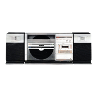
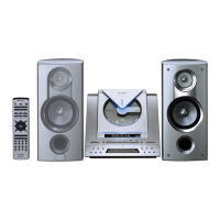
PHOTO:
VZ-1550H
(BK)
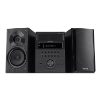
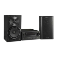
PHOTO:
CP-1550E(BK)
Recording
and
playback
of
any
material
may
require
consent
which
SHARP
are
unable
to
give.
Please
refer
particularly
to
the
provisions
of
Copyright
Act
1956,
the
Dramatic
and
Musical
Performers
Pro-
pa
DOLBY
SYSTEM
®
tection
Act
1958,
the
Performers
Protection
Acts
1963
and
1972
and
to
any
subsequent
statutory
enactments
and
orders.
e@Noise
reduction
system
manufactured
under
license
from
Dolby
Laboratories
Licensing
Corporation,
“Dolby’’
and
the
double-D
ein
the
interests
of
user-safety
the
set
should
be
restored
to
its
symbol
are
trademarks
of
Dolby
Laboratories
Licensing
Corporation.
Original
condition
and
only
parts
identical
to
those
specified
be
e
Gerauschunterdriickungssystem
unter
Lizenz
von
Dolby
Laboratories
used.
Licensing
Corporation
hergestellt.
Das
Wort
‘‘Dolby”’
und
das
Symbol
eim
Interesse
der
Benutzer-Sicherheit
sollte
dieses
Gerat
wieder
auf
des
doppelten
D
sind
die
Warenzeichen
von
Dolby
Laboratories
seinen
urspringlichen
Zustand
eingestellt
und
nur
die
vorge-
Licensing
Corporation.
schriebenen
Teile
verwendet
werden.
@Réducteur
de
bruits
Dolby:
Circuit
fabriqué
sous
licence
des
Dolby
@
Dans
l‘intérét
de
la
sécurité
de
|'utilisateur,
l'appareil
devra
étre
Laboratories
Licensing
Corporation,
Le
mot
“Dolby”
et
le
symbole
reconstitué
dans
sa
condition
premiére
et
seules
des
piéces
double
D
sont
des
marques
déposées
des
Dolby
Laboratories
identiques
a
celles
spécifiées,
doivent
étre
utilisées.
Licensing
Corporation,
©INDEX
TO
CONTENTS
©INHALTSVERZEICHNIS@TABLE
DES
MATIERES
Page
Seite
;
Page
SPECIFICATIONS.
..........4..
2-4
TECHNISCHE
DATEN
...........
2—4
CARACTERISTIQUES
...........
2-4
STRINGING
OF
DIALCORD
.......
2—4
SPANNEN
DER
SKALENSCHNUR
....2—4
PASSAGE
DU
CORDON
DU
NAMES
OF
PARTS
.............
5,6
BEZEICHNUNG
DERTEILE........
5,6
CADRAN............0250005
2—4
DISASSEMBLY.
..............
7-10
ZERLEGEN.............0...
7-10
NOMENCLATURE.
..........005
5,6
BLOCK
DIAGRAM.
..............
11
BLOCKSCHALTPLAN.............
11
DEMONTAGE
...............
7-10
EFFECTIVE
KEY
OPERATION.....
12-14
EFFEKTIVE
TASTENBEDIENUNG.
.
.12—14
DIAGRAMME
SYNOPTIQUE
........
11
FUNCTIONS
OF
MICROCOMPUTER
!C801
FUNKTIONEN
DES
MIKROCOMPUTERS
OPERATION
DE
TOUCHE
AND
ITS
PERIPHERAL
CIRCUIT.
.
.15-17
1C801
UND
SEINER
EFFICACE........
fede
Wd
Se
ea
a
12-14
MECHANICAL
ADJUSTMENT.
.....
18-21
PERIPHERIESCHALTUNG.......
15-17
FONCTIONS
DU
MICRO-ORDINATEUR
STRINGING
OF
PLAYER
WIRE.
....
18,19
MECHANISCHE
EINSTELLUNG
...
.18—21
1C801
ET
DE
SES
CIRCUITS
CIRCUIT
ADJUSTMENT.........
22—25
SPANNEN
DES
PERIPHERIQUES.
............
15-17
NOTES
ON
SCHEMATIC
DIAGRAM...
.
26
PLATTENSPIELERDRAHTS......
18,19
REGLAGE
DE
MECANISME.......
18—21
SCHEMATIC
SCHALTUNGSEINSTELLUNG
.....
22—25
PASSAGE
DU
FIL
DU
LECTEUR...
.18,
19
DIAGRAM.
.......
27,
28,
31,
32,
35,
36
ANMERKUNGEN
ZUM
SCHEMATISCHEN
REGLAGE
DUCIRCUIT.........
22-25
WIRING
SIDE
OF
SCHALTPLAN
.........-..-.0..
26
REMARQUES
CONCERNANT
LE
P.W.BOARD...........
29,
30,
33,34
SCHEMATISCHER
SCHALTPLAN
DIAGRAMME
SCHEMATIQUE.
......
26
EQUIVALENT
CIRCUIT
ee
27,
28,
31,
32,
35,36
DIAGRAMME
(BLOCK
DIAGRAM)
OF
IC.......
37,38
VERDRAHTUNGSSEITE
DER
SCHEMATIQUE.....
27,
28,
31,
32,
35,
36
TYPES
OF
TRANSISTOR
AND
LED....39
LEITERPLATTE........
29, 30,
33,34
COTE
CABLAGE
DE
LA
PLAQUETTE
WIRING
OF
PRIMARILY
SUPPLY
ERSATZSCHALTKREIS
DE
MONTAGE
IMPRIME
. .
.
29,
30,
33,
34
LEADs
(VZ-1550E
ONLY)
.........
39
(BLOCKSCHALTPLAN)
CIRCUITS
EQUIVALENTS
(DIAGRAMME
PACKING
METHOD
(V2-1550E,
DES
INTEGRIERTEN
SYNOPTIQUE)
DECI
..........
37,
38
CP-1550E
ONLY)...
.........-.6-
40
SCHALTKREISES
............
37,38
TYPES
DE
TRANSISTORETLED.....
39
EXPLODED
VIEW.............
41-43
TRANSISTOREN-UND
VUE
EN
ECLATE.............
41-43
REPLACEMENT
PARTS
LIST......
44-50
LEUCHTDIODENTYPEN..........
39
LISTE
DES
PIECES
DE
SERVICE
INFORMATION..........
50
EXPLOSIONSDARSTELLUNG
.....
41-43
RECHANGE............-04.
44-50
ERSATZTEILLISTE............
44-50
INFORMATION
DESERVICE........
50
SERVICE-INFORMATION..........
50
XX
By
SHARP
CORPORATION