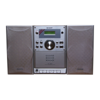
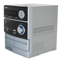
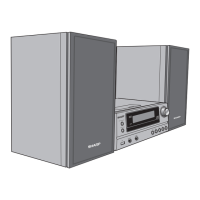
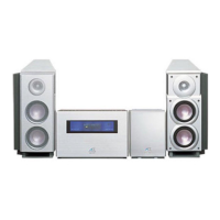
SD-NX10
SERVICE MANUAL
SHARP CORPORATION
No. S0167SDNX10///
• In the interests of user-safety the set should be restored to its original
condition and only parts identical to those specified should be used.
This document has been published to be used
for after sales service only.
The contents are subject to change without notice.
The power of this unit is supplied from the amplifying unit via the
system connection cable. It does not operate by itself.
The Service Manual is for the SD-NX10, which is a minor-modification model of the SD-SG11. This manual, therefore, describes only the
changed points from the service manual. Please refer to the SD-SG11 service manual (S9165SDSG11//) together with this manual.
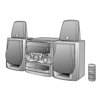
SD-SG11
IMPORTANT SERVICE NOTES (FOR U.S.A. ONLY)........................................................................................................................................ 2
REMOVING AND REINSTALLING THE MAIN PARTS .................................................................................................................................... 15
WIRING PROCESS DIAGRAM ........................................................................................................................................................................ 19
ADJUSTMENT .................................................................................................................................................................................................. 19
ERROR MESSAGE LIST .................................................................................................................................................................................. 29
EEPROM WRITING PROCEDURE .................................................................................................................................................................. 30
DESCRIPTION OF CIRCUIT FOR 1-BIT UNIT ................................................................................................................................................ 32
TO CHECK AND CANCEL PROTECT CIRCUIT DETECTION LINE ............................................................................................................... 33
TEST MODE ..................................................................................................................................................................................................... 34
WAVEFORMS OF 1-BIT CIRCUIT ................................................................................................................................................................... 75
WAVEFORMS OF MD CIRCUIT ...................................................................................................................................................................... 76
CD OPTICAL PICKUP LENS CLEANING ........................................................................................................................................................ 78
TROUBLESHOOTING ...................................................................................................................................................................................... 79
FUNCTION TABLE OF IC................................................................................................................................................................................. 83
FL DISPLAY ...................................................................................................................................................................................................... 96
CONTENTS
Page
SPECIFICATIONS ............................................................................................................................................................. 2
NAMES OF PARTS ........................................................................................................................................................... 3
OPERATION MANUAL ...................................................................................................................................................... 6
DISASSEMBLY................................................................................................................................................................ 11
NOTES ON SCHEMATIC DIAGRAM .............................................................................................................................. 15
TYPES OF TRANSISTOR AND LED............................................................................................................................... 15
BLOCK DIAGRAM ........................................................................................................................................................... 16
WIRING SIDE OF P.W.BOARD ....................................................................................................................................... 23
SCHEMATIC DIAGRAM .................................................................................................................................................. 34
VOLTAGE ........................................................................................................................................................................ 48
FUNCTION TABLE OF IC................................................................................................................................................ 49
PARTS GUIDE/EXPLODED VIEW
PACKING OF THE SET (FOR U.S.A. ONLY)
SD-NX10
MODEL
1-BIT DIGITAL AUDIO SYSTEM
SD-NX10 1-bit Digital Audio System consisting of SD-NX10 (MD/
CD/TUNER unit), SD-NX10 (amplifier unit) and CP-NX10 (speaker
system).