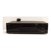
Do you have a question about the Sherwood RV-4050R and is the answer not in the manual?
| Channels | 2 |
|---|---|
| Frequency Response | 20Hz to 20kHz |
| Signal to noise ratio | 95dB (line) |
| Weight | 9.5 kg |
| Tuning range | FM, AM |
| Input sensitivity | 150mV (line) |
| Output | Headphones |
| Power Output | 100 watts per channel into 8Ω (stereo) |
Specifies performance for normal audio output, including power and distortion limits.
Details Dolby-logic mode specifications for audio output power and signal-to-noise ratio.
Lists specifications for the center audio channel output, including power and noise levels.
Provides specifications for the rear audio channels, focusing on output power and noise.
Covers general specifications like speaker load impedance and power consumption.
Outlines detailed technical specifications for the FM tuner section.
Details specifications related to the multiplex (MPX) stereo decoding section.
Lists technical specifications for the AM tuner section, including sensitivity and selectivity.
Describes the pin configuration and function of the main microprocessor IC501.
Lists the necessary test equipment for performing alignment procedures.
Identifies specific test points on the tuner PC board for alignment.
Details the steps for aligning the AM Intermediate Frequency (IF) and Radio Frequency (RF) stages.
Outlines the procedure for aligning the FM Intermediate Frequency (IF) stage.
Describes the steps for aligning the FM Multiplex (MPX) section.
Addresses issues where the receiver is dead and the front light indicator is off.
Covers troubleshooting steps when the main fuse repeatedly blows upon power-up.
Explains causes and remedies for no audio output on either channel when the FL indicator is lit.
Details troubleshooting for a single dead audio channel, tested with a signal at the volume control.
Diagnoses problems where speakers function but headphone output is dead.
Provides solutions for when the FM reception or playback is not functioning.
Addresses issues with weak stereo separation in FM reception.
Troubleshoots why the stereo indicator fails to illuminate during FM reception.
Covers causes for low or insufficient volume specifically from the FM tuner section.
Addresses issues where the FM mono selection switch does not alter the audio output.
Provides troubleshooting steps for when the AM tuner section fails to operate.
Diagnoses problems where bass or treble tone controls are unresponsive.
Explains why automatic or manual tuning functions might fail.
Covers troubleshooting for a non-functional FL display and remote control unit.
Lists included accessories such as antennas, batteries, and manuals.
Details parts related to the unit's physical enclosure and structural components.
Provides pinout and internal diagram for the GD4066B IC, used for switches.
Details lead identification and block diagrams for OP AMP ICs like KIA4559P.
Shows the package outline and block diagram for the LA1266 IC.
Provides the package outline and block diagram for the LM7001 IC.
Details pinout and block diagram for the NJM2177L IC, likely audio processing.
Shows lead identification and block diagram for the TC9176P IC.
Provides lead identification and block diagram for the LC7821 IC.
Details pinout and block diagram for the KA2265 IC, related to FM/AM tuning.
Shows pinout and block diagram for the NJU9701 IC, likely for digital delay.
Identifies lead configurations for KTB688/2SB688 and KTD718/2SD718 transistors.
Shows lead identification for KTB1367/2SB1367 and KTD2059/2SD2059 transistors.
Details the front and bottom view lead identification for the 2SC4137 transistor.
Lists lead identification for several KTA, KTC, and KTD series transistors.
Identifies lead configurations for KTC114YS and KTA114YS transistors.
Shows lead identification for KTA949/KTA1024 and KTC2229/KTC3206 transistors.
Details the lead identification for the 2SK117 transistor.
 Loading...