109823 2/09 4-1
SECTION 4: ENGINE RE-ASSEMBLY
Caution: before assembling engine;
1. Clean parts to be installed. (Especially oil passages, bearings, pistons, and cylinder bores
carefully.)
2. Coat the sliding and rotating parts of the cylinder bore, piston, bearing and other parts with
new oil before installing.
3. Use new gaskets. If necessary, use gasket sealants to prevent oil leakage.
4. Do not tighten bolts and nuts for aluminum alloy parts excessively. Tighten them to speci-
fied torque.
Relief valve assembly with O-Ring.
Relief valve, torque to:
41.3-48.3 lb
f
•ft (59–69 N·m) {6.0–7.0 kgf·m}
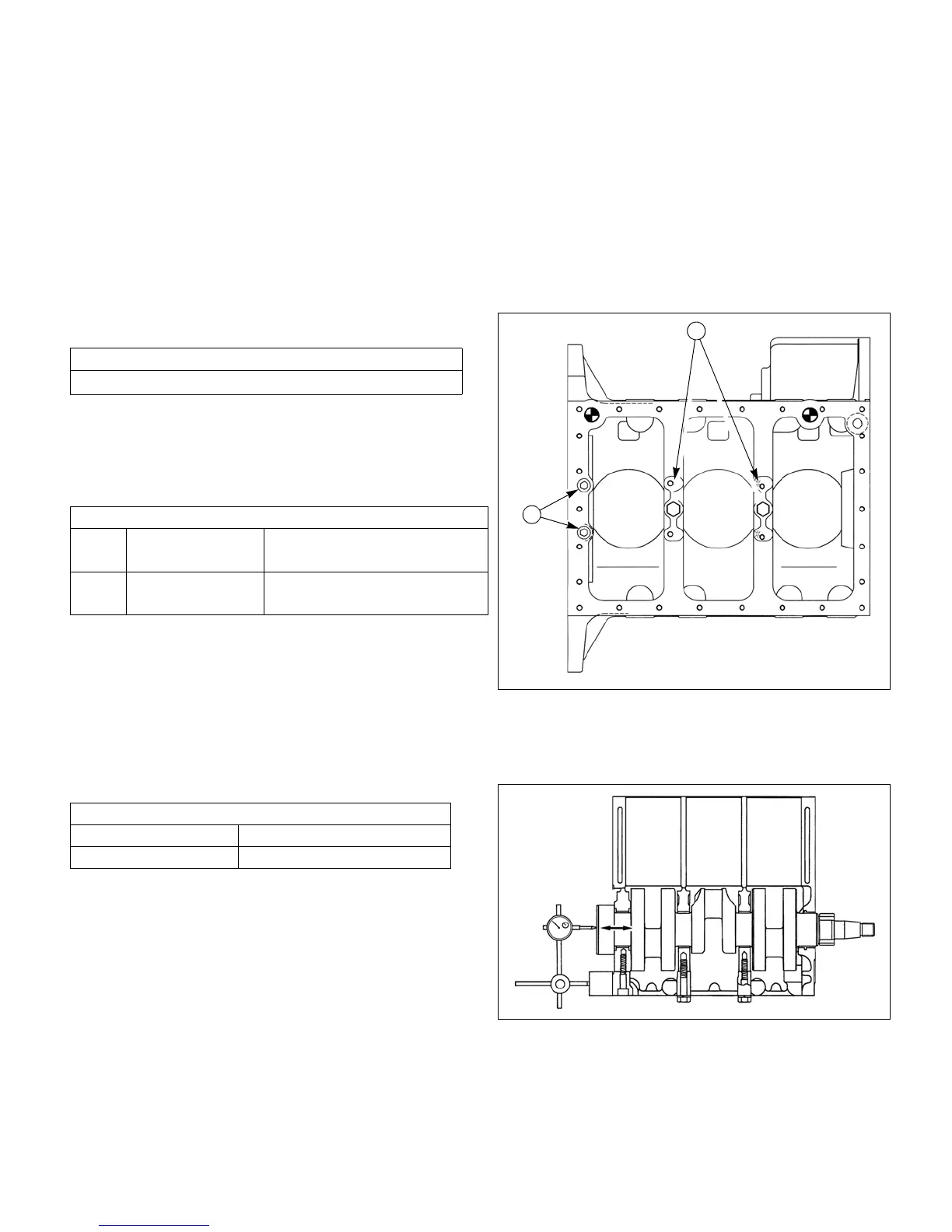
Crank shaft and bearing holder assembly
Cylinder block to bearing holder torque
Notes: 1. Be careful not to damage the bushing in the
cylinder block by the crankshaft gear when
install the crankshaft and bearing holder
assembly.
2. Install the two hexagon socket head bolts
for the flywheel side bearing holder.
Measure the end play of crankshaft.
Relief valve torque
43.5-50.9 lb
f
•ft (59-69 N·m) {6.0-7.0 kgf·m}
Bearing holder bolts
A Hexagon socket
head bolt
17.5-20.3 lb
f
•ft (25–29 N·m)
{2.5–3.0 kgf·m}
B Hexagon bolt 17.5-20.3 lb
f
•ft (25–29 N·m)
{2.5–3.0 kgf·m}
Crankshaft end play
Standard value 0.004-0.012 (0.1–0.3)
Service limit More than 0.020(0.5)


 To Next Page