5-2 109823_2/09
Testing
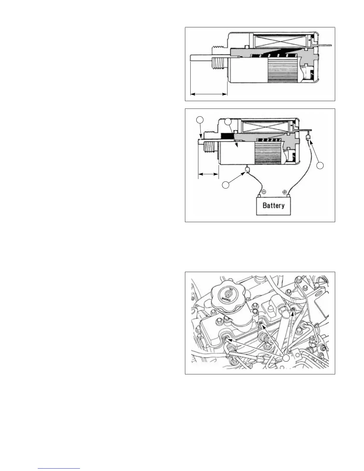
1. Using a suitable measuring device, measure the
protrusion distance, “A” ( page 5-2, Fig. 5-3), on the
solenoid. The distance should measure between
1.00–1.04 in.(25.5 - 26.4 mm). If the distance is not
within these specifications, the solenoid is defective
and needs replaced.
Note: When connecting the 12-volt power supply
to the solenoid body, be sure paint is
removed from the body. Otherwise, the
power will not be transferred to the
solenoid.
2. Use jumper wires to connect the positive (+) terminal
of a 12-volt power supply to the solenoid lead,
(
page 5-2, Fig. 5-4). Connect the negative terminal of
the 12-volt power supply to the solenoid body,
(
page 5-2, Fig. 5-4). The plunger,
( page 5-2,
Fig. 5-4), should retract into the solenoid body.
3. Using a suitable measuring device, measure the
protrusion distance, “B” on the solenoid. The
distance should measure between 0.45–0.57 in.
(11.5 - 14.5 mm). If the distance is not within these
specifications or the plunger does not retract, the
solenoid is defective and needs replaced.
Installation
1. Assembly of the engine stop solenoid generally
follows the disassembly in reverse, using a new
sealing washer,
( page 5-1, Fig. 5-2), on the
solenoid,
( page 5-1, Fig. 5-2).
Engine Glow Plugs
Description
The engine glow plugs
are located on the right side of
the engine cylinder head, near the fuel injectors.
The glow plugs are used to preheat the air in the pre-
combustion chamber. This aids in the starting of the engine
when cold.
Removal
1. Disconnect the negative (–) battery cable from the
battery.
2. Remove the three (3) nuts,
( page 5-3, Fig. 5-6),
and washers securing the electrode bar,
( page
5-3, Fig. 5-6), from the glow plugs.
3. Remove the glow plugs from the engine cylinder
head.
Engine Glow Plug Testing
1. Clean carbon from the sheath end of the glow plug.
Note: Do not test resistance using the glow plug
sheath.


 To Next Page