109823_2/09 5-17
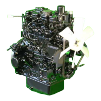
b. Push pinion back by hand and measure the
amount of the pinion movement as shown in page
5-17, Fig. 5-35. If the amount does not fall within
limit, adjust it by adding or removing shims which
are located between switch and front bracket.
Adding shims decreases the amount of the
movement.
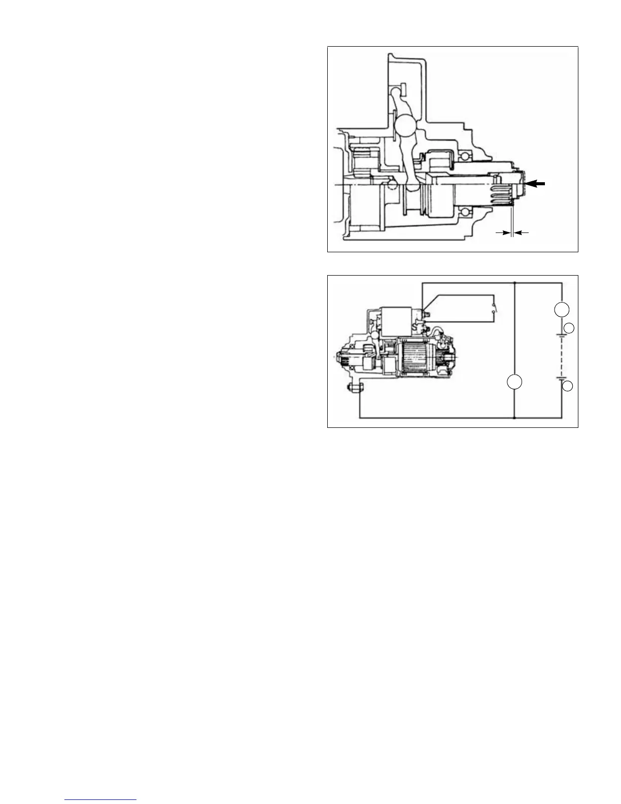
Non-load test
1. After adjusting pinion position, from a test circuit with
a voltmeter and an ammeter, as shown in page
5-17, Fig. 5-36.
Note: Use wires as thick as possible and tighten
each terminal.
2. Close the switch and compare the R.P.M. current
and voltage readings with the specifications in page
7-1, Section 7:Servicing Specifications.
3. If any abnormality is noted, check it according to the
procedures on page 5-15, Inspection.
 Loading...