CONTROLS, INSTRUMENTS AND OPERATIONS
15
ELECTRICAL SOCKET for Traile
r
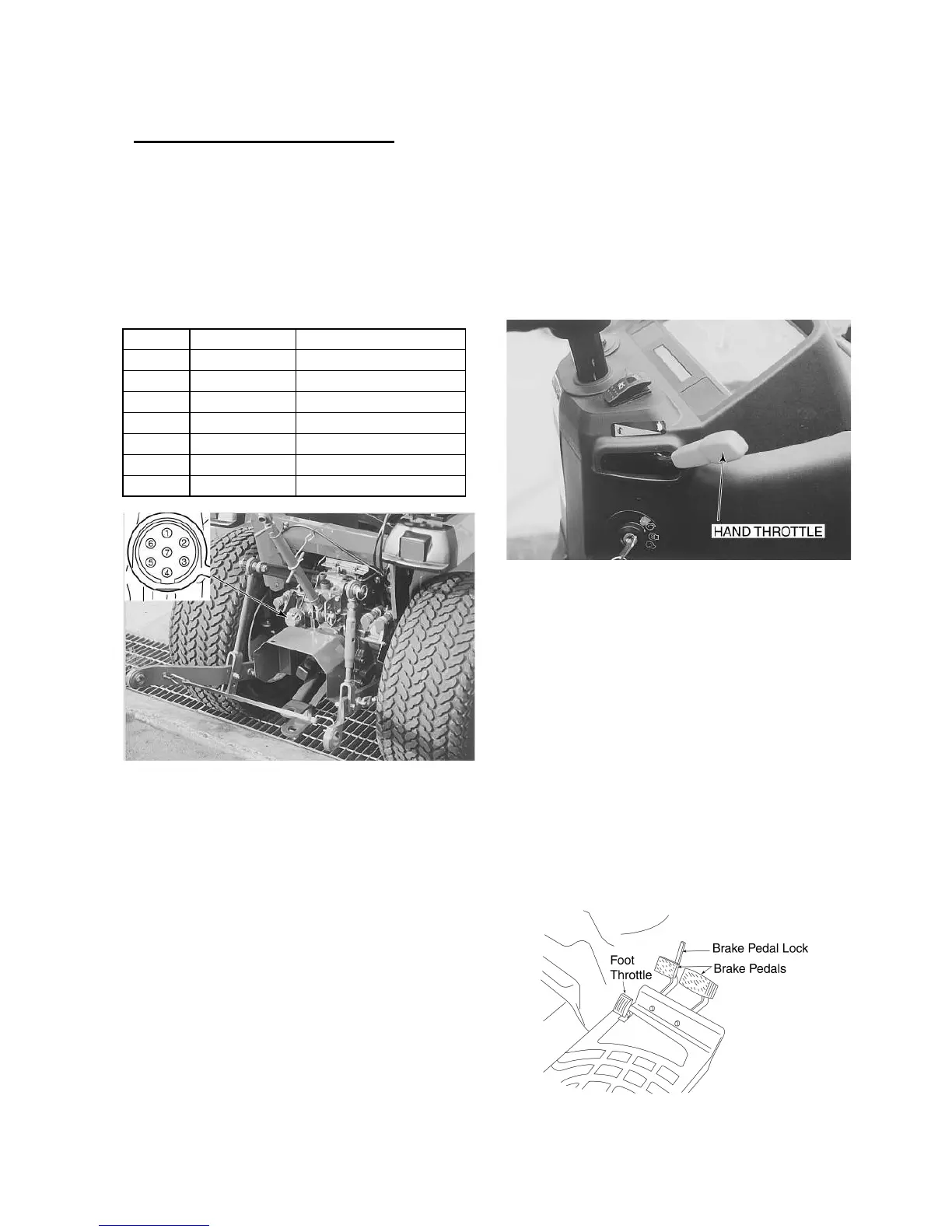
A standard seven pin socket, Figure 12, is provided
mounted on the left side of the tractor at the rear.
With reference to the picture inset, the socket
connections (as viewed from the rear of the tractor)
are as follows;
Pin No. Wire Colour Circuit
①
Green/Red L.H. Turn Signal
② Not Used
③ Black Earth(Ground)
④ Green/White R.H. Turn Signal
⑤ Red R.H. Parking Light
⑥ Green/Purple
Stop Lights
⑦ Red/Black L.H. Parking Light
Figure 12- Seven Pin Electrical Socket
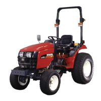
THROTTLE CONTROLS
HAND THROTTLE AND ENGINE STOP
CON-
TROL
The hand throttle is shown in Figure 13. Push the
throttle rearward to increase engine rpm. Pull the
throttle forward to decrease engine rpm.
Figure 13 - Hand throttle
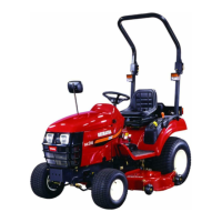
FOOT THROTTLE
(Only mechanical transmission, 9x3)
The foot throttle, shown in Figure 14, can be used
separately, or in conjunction with the hand throttle.
With the hand throttle control lever set at a selected
engine rpm, the foot throttle can be used to in-
crease engine rpm to its maximum speed.
Upon release of the foot throttle, the engine speed
will return to the rpm at which the hand throttle has
been set, or idle if the hand throttle is not at a
pre-set position.
Figure 14 - Foot throttle and Brake Controls