CONTROLS, INSTRUMENTS AND OPERATIONS
24
HYDURAULIC LIFT SYSTEM
Hydraulic Power Lift (HPL)
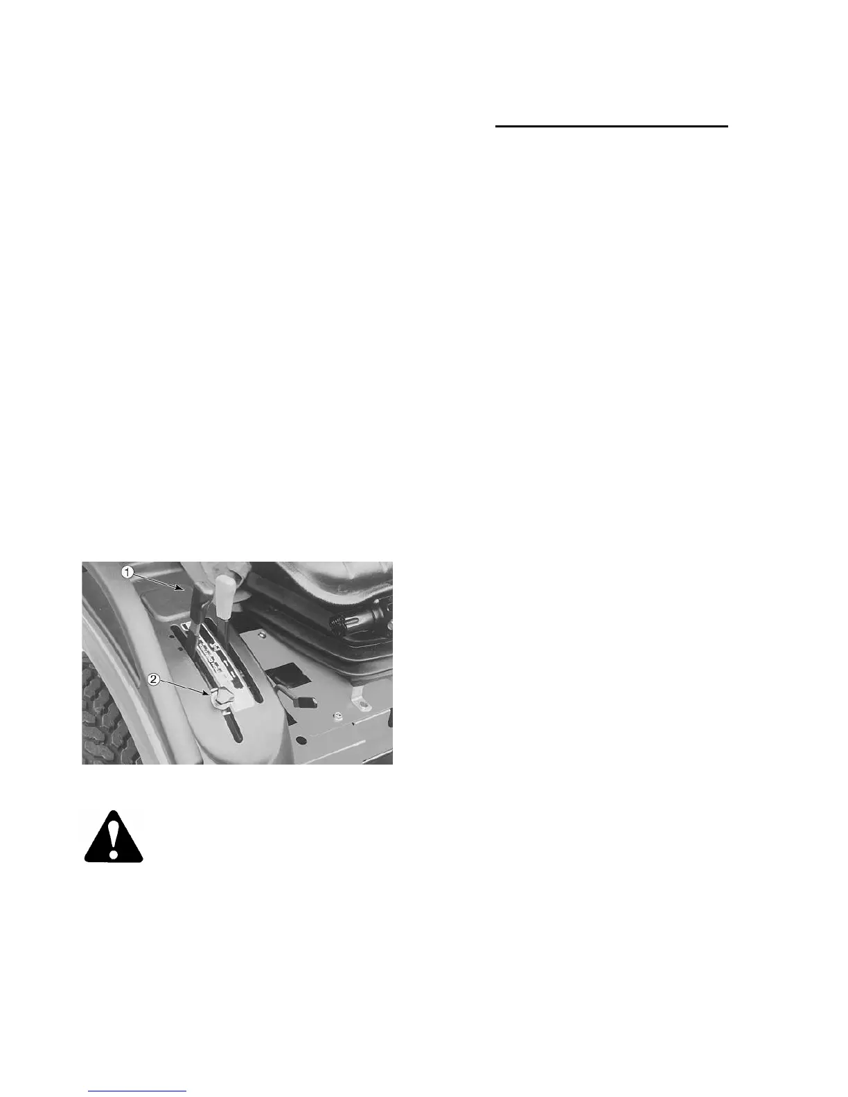
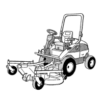
The hydraulic Power lift (H.P.L.) is located on the
right-hand control pod, Figure 34. The lever con-
trols the position of the two lift arms. To lower the
lift arms, move the H.P.L. lever ①, forward. To
raise the lift arms, move the lever rearward. An
adjustable stop ②, Figure 34, is located in the
quadrant allowing the lever to be returned to a preset
position.
The hydraulic lift system provides accurate, smooth,
and instant hydraulic power for raising a variety of
compatible equipment whenever the engine is run-
ning. The position control feature of the system
maintains the selected height or depth of
three-point linkage equipment in relation to the
tractor. When the hydraulic lift control lever is
moved to a higher or lower setting in the quadrant,
the system repositions the equipment to a higher or
lower position and maintains the selected position,
Figure 34.
Figure 34 - Hydraulic Lift System Control
WARNING:
::
:Make sure area is clear of
people before lowering equipment.
Position Control
Position control provides easy, accurate control of
three-point linkage equipment witch operates
above the ground, such as sprayers, rakes, mow-
ers, etc.
It also provides uniform depth when using a blade
or other soil engaging equipment.
When operating in position control, there is a defi-
nite relationship between the position of the control
lever in the quadrant and the position of the equip-
ment.
The lever must be moved to change the position of
the equipment relative to the tractor. The system
will automatically maintain the equipment in the
selected position.
H
.
P.L. LEVER POSITIN ADJUSTMENTS
Linkage Adjustment
The length of the position control is critical and
careful adjustment must be observed for proper
operation. If the control rod adjusted too short, the
control valve spool will remain in the raised position
when the lift arms have reached their maximum
height and the system relief valve will below. If the
control rod is too long, the control valve spool will
return to neutral before the lift arms reach their full
height.
The position control rod should be adjusted any
time the link is disconnected for service to the hy-
draulic system, or any time the relief valve opera-
tion is noticed while the lift arms are at the full raise
position.
Adjustment Procedure
1. Loosen the lock-nut ①, on the position control rod ②,
and remove the rod from the lift arm ③.
2. Set the control lever ④, to the highest position.
3. Start the engine. The lift arms should raise and
the relief valve should operate.
4. Move the control lever forward until the relief
valve stops operating.
5. Adjust the length of the position control rod to
align the rod with the hole in the lift arms. Then
extend the rod one additional complete turn.
Install the cotter pin and tighten the nuts.