CONTROLS, INSTRUMENTS AND OPERATIONS
25
6. Check the operation. The relief valve should not
operate with the arms fully raised.
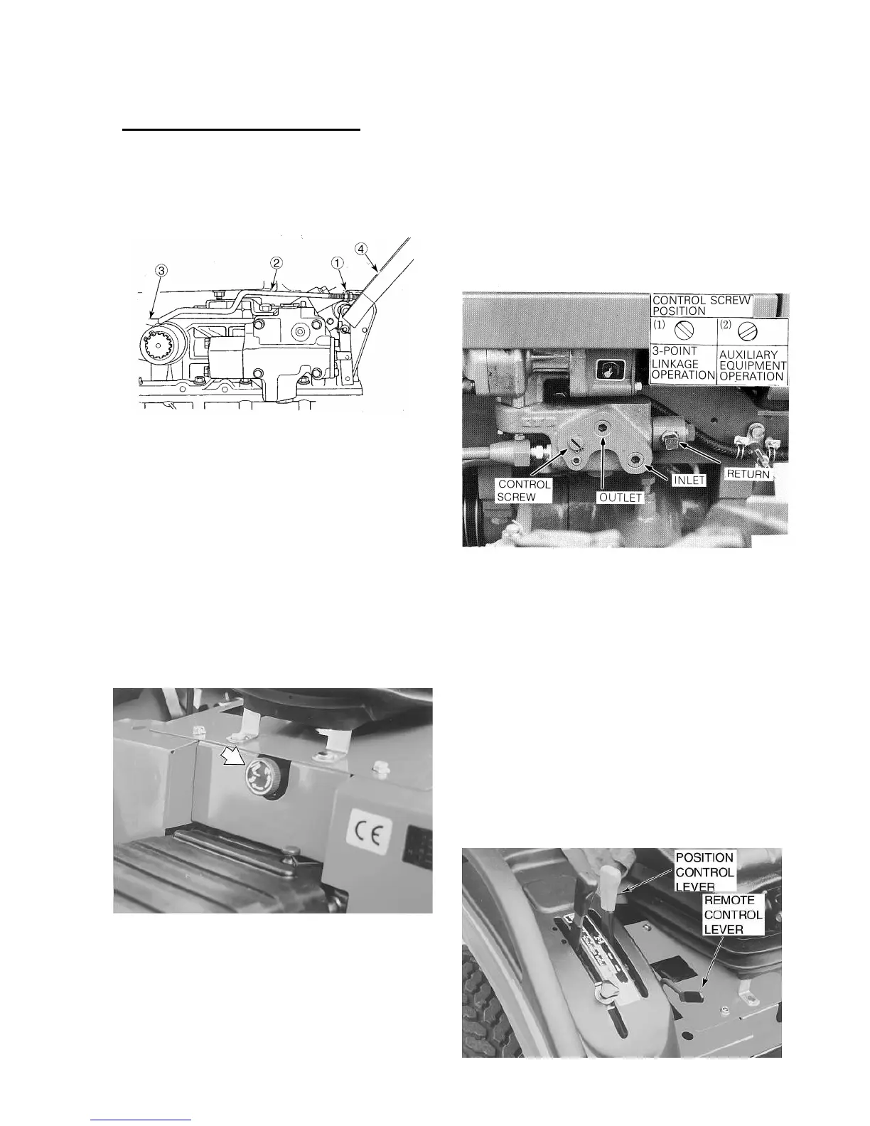
Figure 35 - Linkage Adjustment
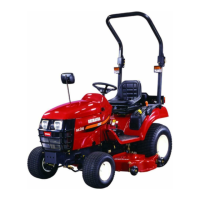
FLOW CONTROL VALVE
The flow control valve, Figure 36, provides an ad-
justment to regulate the flow of oil from the lift cyl-
inder, thus slowing or increasing the rate of drop of
the lower links.
To adjust rate of flow, either turn the flow control
valve “IN”(clockwise) to decrease the rate of drop
or “OUT”(counterclockwise) to increase the rate of
drop. The flow control valve must be opened before
hydraulic lift control will function.
Figure 36 - Flow Control Valve
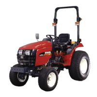
HYDRAULIC MANIFOLD BLOCK/DIVERTER
The hydraulic Manifold Block is provided to supply
hydraulic oil to equipment such as a front loader,
dozer blade, etc. Location of the Block is shown in
Figure 37.
To operate auxiliary equipment, remove the plugs
from the manifold block and connect the feed hose
to the outlet port, Figure 37and the return hose to
the inlet port.
Figure 37 - Hydraulic Manifold Block
IMPORTANT:
::
:In order to operate auxiliary equip-
ment, the control screw must be turned to the
position shown at (2). With a front remote valve in-
stalled, it is not required to turn the control screw to
the position shown at (1) to operate the three point
linkage only, the screw must be turned to the posi-
tion shown at (1).
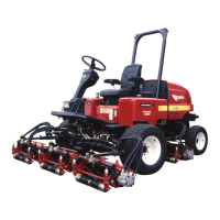
REAR REMOTE CONTROL VALVES
(OPTIONAL)
Your SHIBAURA tractor can be equipped with a
single and/or double spool remote control valves.
Figure 38 shows the operation of the single spool
and double spool valves.