CONTROLS, INSTRUMENTS AND OPERATIONS
21
The differential lock is engaged by depressing the
pedal located on the right side of the rear axle
center housing on tractor with mechanical trans-
mission, Figure 26.
The differential lock pedal is located on the left side
of the rear axle center housing on tractor with op-
tional H.S.T. transmission.
Depressing the pedal locks both final drive pinion
gear shafts together, preventing one wheel from
rotating independently of the other.
The lock should be used to obtain additional trac-
tion from the opposite wheel whenever one wheel
begins to slip in wet or loose soil.
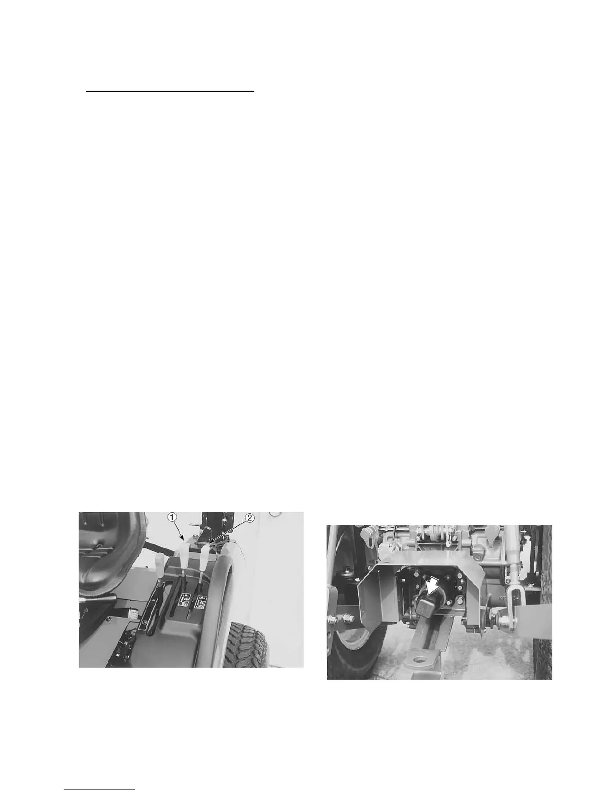
TRANSMISSION PTO CONTROL LEVER
The transmission rear PTO and mid PTO (if
equipped) control levers are shown in Figure 27 .
One engages and disengages the rear PTO and
the other operates the mid PTO (if equipped).
If the tractor engine is running, always depress the
clutch pedal fully before moving the lever.
Move the lever up to engage the rear PTO or mid
PTO and down to disengage the rear PTO or mid
PTO
Figure 27 - PTO Control Lever,
1. Rear PTO Lever, 2. Mid PTO Lever
POWER TAKE-OFF
The power take-off (PTO) in your tractor transfers
engine power directly to PTO equipment. The stan-
dard PTO speed is 540 ± 10 rpm.
Most PTO equipment is designed to operate effi-
ciently at this speed. This speed is obtained when
engine rpm is as indicated by the PTO symbol on
the Proof-Meter rpm scale.
IMPORTANT:
::
:Do not exceed 2388 rpm or 2503
rpm (if H.S.T. equipped) engine speed when oper-
ating PTO - driven equipment.
The optional mid PTO speed is 2000±10 rpm. This
speed is obtained when engine rpm is set at 2432
or 2550(if H.S.T. equipped) rpm. The transmission
rear PTO is controlled through a lever shown in
Figure 27. The transmission PTO can be engaged,
operated, and disengaged as described under
“POWER TAKE-OFF OPERATION.”
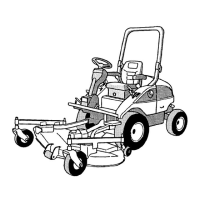
PTO SHIELD AND CAP
The PTO shield, shown in Figure 28, is standard
equipment. The shield is to be used with all PTO
equipment. The PTO cap should always be in-
stalled when the PTO is not in use.
Figure 28 - PTO Shield and Cap