CONTROLS, INSTRUMENTS AND OPERATIONS
27
On the single spool valve, pull the control lever
rearward to extend the cylinder. Push the control
lever forward to retract the cylinder. Release the
control lever to stop the cylinder in any position
before it is fully extended. The lever returns to
neutral automatically.
For the double spool valve pull the control lever
rearward or push it sideways to the right to extend
the cylinder. Push the control lever forward or pull
it sideways to the left to retract the cylinder.
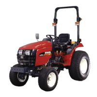
HYDRAULIC COUPLINGS
Viewed from the rear of the tractor, the couplings
①, for the optional double acting remote valve are
located on the right of the top link support bracket,
Figure 39. The couplings will accept standard 1/2
inch male implement connectors.
Mounted to the left of the to link support bracket,
the ASC valve coupling ②, provide a high pres-
sure oil supply for tipping trailers or operating sin-
gle acting cylinders. A 3/8 inch coupler is used for
the ASC valve.
Figure 39 - Hydraulic Couplings
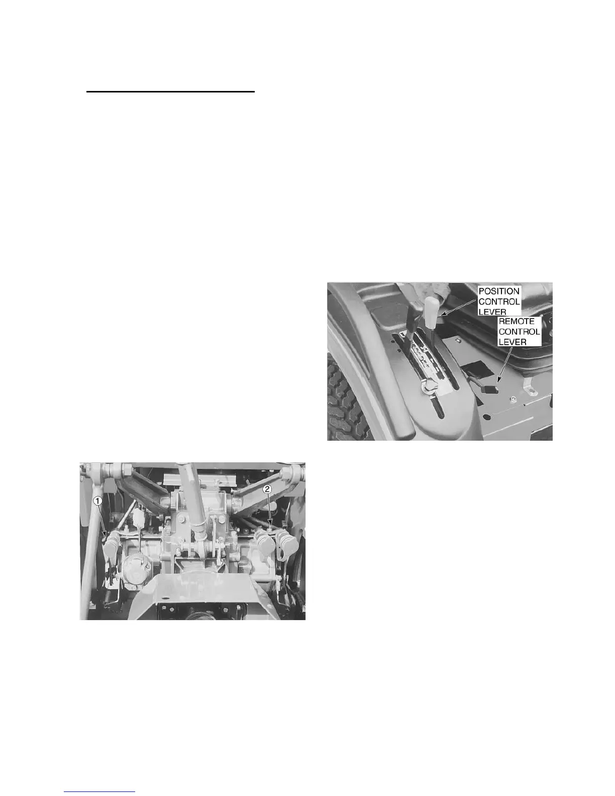
AUXILIARY SERVICE CONTROL (ASC) VALVE
To operate the ASC valve, remove the position
control lever, shown in Figure 40, to the to of the
quadrant against the spring pressure. Holding the
lever in this position will generate a flow of pres-
surized oil to the
implement via the single connector, Figure 40, at
the rear of the tractor. To halt the oil flow, allow the
spring pressure to move the lever to the “Neutral”
position at the top of the quadrant. To retract the
extended implement cylinder, move the lever to the
bottom of the quadrant.
Figure 40 - Auxiliary Service Control Valve (ASC)