70(96)
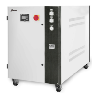
2.2.52 General Assembly Diagram Parts List (SIC-114A-R2)
Table 2-26:General Assembly Diagram Parts List (SIC-114A-R2)
No.
Name Stock No.
1
Rack - 13 Water pressure gauge YW85001000100
2 Side plate 2 - 14 Lower door plate -
3 Side plate 1 - 15 Back plate 2 -
4 Fan YM60650650000
16 Back plate 3 -
5 Air guide - 17 Refrigerant indicator base
6 Back plate 1 - 18
Regrigerant indicator
screw
BH12060700110
7
Socket head cap
screw M6×65
YW61066500100
19
Refrigerant indicator
STM-310
BH12030000010
8
High pressure
gauge
YW85005500000
20 Glass tube YW70963000000
21 Refrigeration indicator BL90006800020
Upper door plate - 22
Refrigerating system
assembly
-
11
Gauge plate - 23
Cross recessed oval head
screw M6×30
YW62063000000
Cross recessed oval
head screw M4×10
YW62041000000
24 Cooling water system -
** means possible broken parts. ** means easy broken parts. Spare backup is suggested.
Please confirm the version number of the manual before you order to ensure the stock
number and the parts are consistent.
 Loading...