1
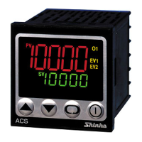
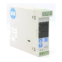
COMMUNICATION INSTRUCTION MANUAL ACS-13A (C5)
No. ACS12CE5 2019.08
This manual contains instructions for communication functions of the ACS-13A.
Serial communication and Console communication cannot be used together.
When performing Serial communication, remove the exclusive cable (CMA) from the USB port of the PC and
loader connector of the ACS-13A.
When performing Console communication, it is not required to remove the Serial communication cables.
However, do not send a command from the master side.
1. System Configuration
(Fig. 1-1)
2. Wiring
When using communication converter IF-400
[D-sub 25-pin connector] [D-sub 9-pin connector]
Shield wire
Connect only one end of the shield to the FG to avoid a ground loop. If both ends of the shield wire are
connected to the FG, the circuit will be closed, resulting in a ground loop. This may cause noise.
Be sure to ground the FG.
Recommended cable: OTSC-VB 2PX0.5SQ (made by Onamba Co., Ltd.) or equivalent (use a twisted pair
cable.)
Terminator (Terminal resistor)
Communication converter IF-400 (sold separately) has a built-in terminator.
The terminator is mounted at the end of the wire when connecting multiple peripheral devices to a personal
computer. The terminator prevents signal reflection and disturbance.
Do not connect the terminator to the communication line because each ACS-13A has built-in pull-up and
pull-down resistors.
Communication converter IF-400
RS-232C RS-485
No. 0
No. 1
No. 30
ACS-13A (Max. 31 units)
wire
wire