3
Shield wire
Be sure to ground only one end of the shield wire to avoid a ground loop. If both ends of the shield
wire are grounded, the circuit will be closed, resulting in a ground loop. This may cause noise.
Recommended cable: OTSC-VB 2PX0.5SQ (made by Onamba Co., Ltd.) or equivalent
(Use a twisted pair cable.)
Terminator (Terminal resistor)
The terminator is mounted at the end of the wire when connecting multiple peripheral devices to a
personal computer. The terminator prevents signal reflection and disturbance.
Do not connect a terminator to the communication line because each DCL-33A has built-in pull-up
and pull-down resistors.
3. Setting Method for Communication
Press and hold the and keys (in that order) together for approx. 3 seconds in the PV/SV
Display. The unit enters Auxiliary function setting mode 1.
Press the key twice.
“Communication protocol” will appear.
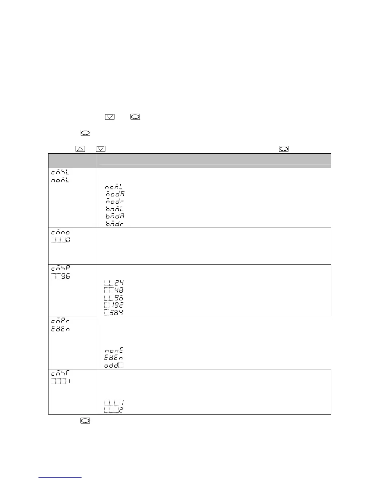
Use the or key for settings or selections, and register them by pressing the key.
Characters,
Factory Default
Setting Item, Function, Setting Range (Selection item)
Communication protocol
• Selects the communication protocol.
• : Shinko protocol
: Modbus ASCII mode
: Modbus RTU mode
: Shinko protocol (Block read)
: Modbus ASCII mode (Block read)
: Modbus RTU mode (Block read)
Instrument number
• Sets the instrument number.
The instrument numbers should be set one by one when multiple instruments are
connected in Serial communication, otherwise communication is impossible.
• Setting range: 0 to 95
Communication speed
• Selects a communication speed equal to that of the host computer.
• : 2400 bps
: 4800 bps
: 9600 bps
: 19200 bps
: 38400 bps
Parity
• Selects the parity.
• Not available if Shinko protocol or Shinko protocol (Block read) is selected in
[Communication protocol].
• : No parity
: Even
: Odd
Stop bit
• Selects the stop bit.
• Not available if Shinko protocol or Shinko protocol (Block read) is selected in
[Communication protocol].
• : 1 bit
: 2 bits
Press the key. The unit reverts to the PV/SV Display.
Now settings are complete.
 Loading...