Shure Incorporated
15/16
Gain Control Connections
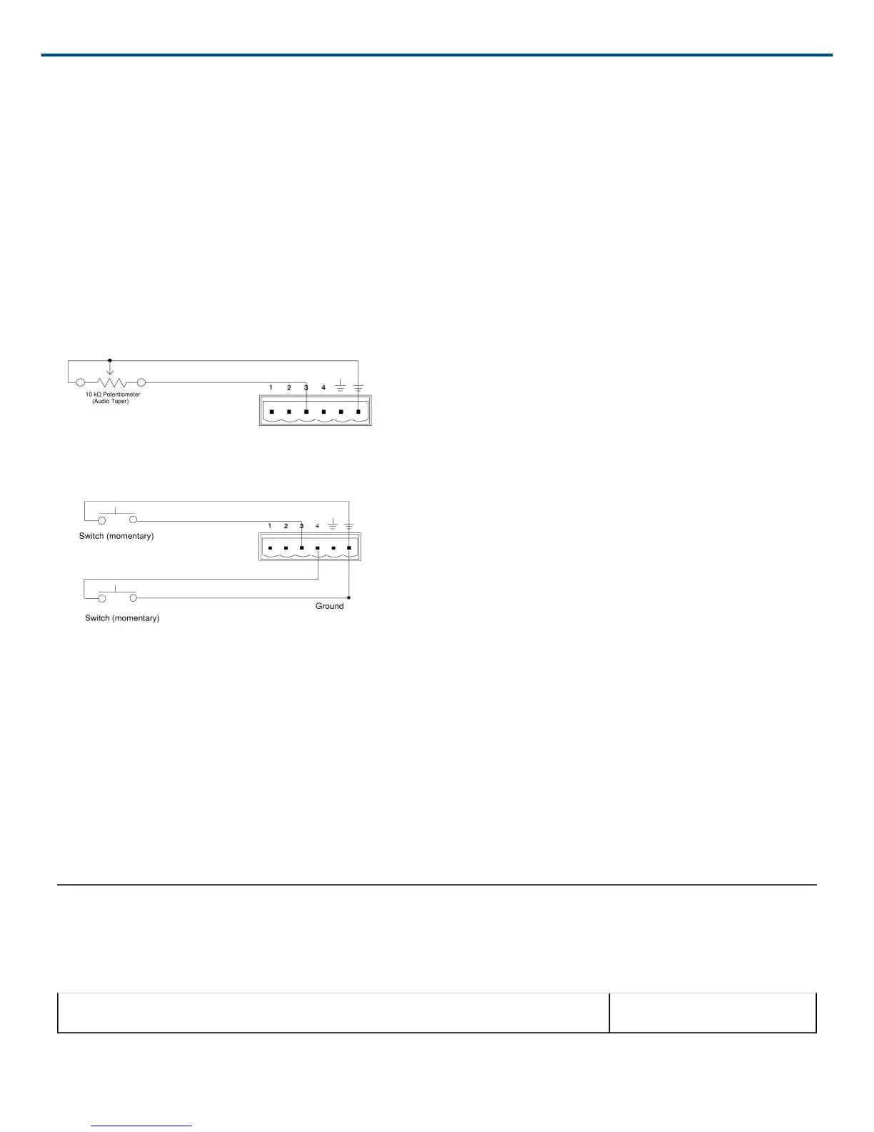
For gain control, use either a potentiometer or two momentary switches (one for gain up and one for gain down). If
you want to have multiple sets of gain controls acting on the same inputs or outputs, use momentary switches con
nected in parallel. Figure 16 shows a typical connection between a potentiometer and the Control Input pins. Fig
ure 17 shows a typical connection between two momentary switches and the Control Input pins.
When using a potentiometer, the total resistance of the cable run should be less than 100 Ω.
When using momentary switches, the total resistance of the cable run should be less than 100 Ω.
As supplied, the DFR22 control pins are configured for use with a 10 kΩ audio taper potentiometer. However, you
can use the Potentiometer Calibration Wizard in the DFR22 software to configure the DFR22 for use with any
10 kΩ, 20 kΩ, 50 kΩ, or 100 kΩ linear or audio taper potentiometer.
Figure 16: GAIN CONTROL PIN CONNECTIONS USING A POTENTIOMETER
Figure 17: GAIN CONTROL PIN CONNECTIONS USING SWITCHES
AMX/Crestron Control Connections
You can connect an AMX or Crestron controller to the back panel RS-232 port, using a Phoenix connector, or to
the front panel RS-232 port, using a DB-9 connector. In either case, you only need to connect three wires: send,
receive, and ground. See page 8 for the pinout of the RS-232 ports.
To access AMX/Crestron control codes for the DFR22, visit the DFR22 web page at http://shure.custhelp.com/
app/answers/detail/a_id/2951
Accessories
Furnished Accessories
Line (Power) Cord (SCM800) 95B8389
 Loading...