

A
Austin BrowningAug 10, 2025
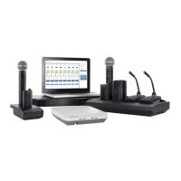
What to do if RF Interference is causing audio drop-outs on Shure MICROFLEX MXW Microphone system?
- CcoxjenniferAug 10, 2025
To resolve RF interference causing audio drop-outs in your Shure Microphone system: * Perform a Spectrum Scan to monitor RF interference. * Decrease channel count to verify if the system is overloading the RF spectrum.