
M
Mercedes TorresAug 5, 2025
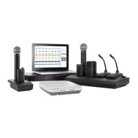
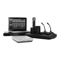
How to fix no or distorted audio on Shure Microflex MXW6/O-Z10?
- MMargaret ThomasAug 6, 2025
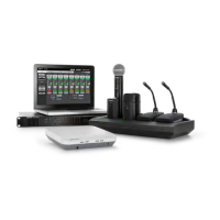
If you are experiencing no or distorted audio with your Shure Microphone system, begin by checking the cables and ensuring they are properly connected. Verify that the transmitters are powered on and that the channels are not muted. Also, check the input meters on the Monitor tab of the MXW control software. If the channel is clipping, attenuate it.